Turbine compressor self-balancing cooling system and method

A technology for turbo compressors and cooling systems, applied in mechanical equipment, engine components, machines/engines, etc., can solve the problems of high design and processing difficulty, high price, inability to design thrust bearings that meet technical requirements, etc. desired effect

Pending Publication Date: 2019-08-16
CHONGQING JIANGJIN SHIPBUILDING IND
View PDF0 Cites 0 Cited by
  • Summary
  • Abstract
  • Description
  • Claims
  • Application Information

AI Technical Summary

Problems solved by technology

Although this method can solve the problem within a certain pressure and temperature range, as the temperature and pressure continue to increase, the design and processing of thrust bearings that meet the conditions are not only very difficult, but also very expensive, and it is even impossible to design a thrust bearing that meets the technical requirements. thrust bearing

Method used


Image

  • Turbine compressor self-balancing cooling system and method

Examples


Embodiment Construction

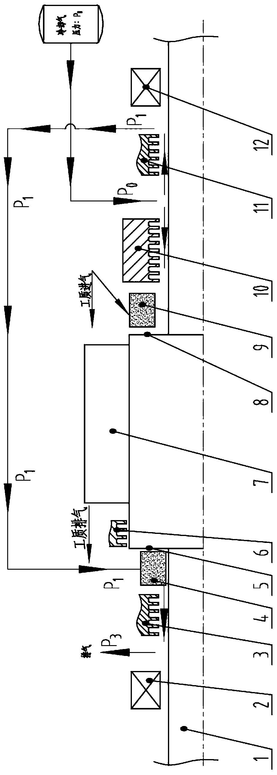
[0015] Such as figure 1 As shown in the figure, a self-balancing cooling system of a turbocompressor includes shaft 1, low-pressure end seal 2, low-pressure section cooling zone 3, low-pressure end pressure balance chamber 4, low-pressure side pressure forming surface 5, and low-pressure end mechanical seal 6 , Moving and stationary vane area 7, high pressure side thrust forming surface 8, high pressure end pressure balance chamber 9, high pressure end mechanical seal 10, high pressure section cooling zone 11, high pressure end seal 12. The pressure balance chamber 4 at the low-pressure end is a chamber between the cooling zone 3 of the low-pressure end and the mechanical seal at the low-pressure end. The pressure balance chamber 4 at the low-pressure end is connected to the pressure balance chamber 9 at the high-pressure end through structural passages.

[0016] The shaft 1 is provided with a large-diameter section with an increased diameter, the low-pressure end mechanical ...


PUM


Abstract

The invention discloses a turbine compressor self-balancing cooling system and method which balance the axial force through the cooling system. According to the turbine compressor self-balancing cooling system and method, by means of control of flowing of high-pressure and low-temperature cooling gases, a shaft can be cooled, and the axial force also can be balanced. The cooling system comprises the shaft and the shaft, a low-pressure end seal, a low-pressure segment cooling area, a low-pressure end pressure balancing cavity, a low-pressure side thrust forming surface, a low-pressure end mechanical seal, a dynamic and static blade area, a high-pressure side thrust forming surface, a high-pressure end pressure balancing cavity, a high-pressure end mechanical seal, a high-pressure segment cooling area and a high-pressure end seal which are arranged on the shaft in sequence, wherein a cooling gas inlet is arranged between the high-pressure end mechanical seal and the high-pressure segmentcooling area to be used for being connected with a cooling gas source, a cooling gas outlet is arranged between the high-pressure segment cooling area and the high-pressure end seal and is connectedwith the low-pressure end pressure balancing cavity through a structural passage, and a cooling gas discharging mouth is arranged between the low-pressure end seal and the low-pressure segment coolingarea to be used for discharging the cooling gases.

Description

technical field [0001] The invention relates to the fields of high-temperature and high-pressure turbines and high-temperature and high-pressure compressors, in particular to a method for balancing axial force in a shaft cooling system of a high-temperature and high-pressure turbine unit or a high-temperature and high-pressure compressor unit. Background technique [0002] In order to improve the overall efficiency of turbine units and compressor units, more and more new working media are used in turbine units and compressors, such as supercritical CO2, ultra-supercritical CO2, helium, etc. These media generally have high pressure , High temperature characteristics. Therefore, the bearings of the turbine unit and the compressor unit are subject to great axial force and super high temperature. The conventional solution is to cool the shaft of the turbine unit through the cooling system, and then balance the axial thrust of the unit by increasing the bearing capacity of the t...

Claims


Application Information

Patent Timeline
Patent Type & Authority Applications(China)
IPC IPC(8): F01D25/12F01D11/00F04D29/58F04D29/10F04D29/051
CPCF01D11/003F01D25/12F04D29/051F04D29/102F04D29/582
Inventor 但光局侯春峰何晓燕龚由春李扬
Owner CHONGQING JIANGJIN SHIPBUILDING IND
Why Eureka
Try Eureka