A low-temperature condensate treatment process and device for a deoiling and dehydrating device in a natural gas treatment plant

A technology of dehydration device and treatment device, which is applied in the petroleum industry, gas fuel, fuel, etc., can solve the problem that the discharged mixed gas cannot meet the requirements of the hydrocarbon dew point of the fuel gas, and achieve significant energy saving effect, reduce heat load, and reduce investment. Effect

Active Publication Date: 2019-06-04
XIAN CHANGQING TECH ENG
View PDF4 Cites 0 Cited by
  • Summary
  • Abstract
  • Description
  • Claims
  • Application Information

AI Technical Summary

Problems solved by technology

[0009] The purpose of the present invention is to solve the problem of a large amount of condensate precipitation in the fuel gas system in the prior art, and the exhausted mixed gas produced by the low-temperature condensate cannot meet the requirements of the dew point of fuel gas hydrocarbons. Therefore, the present invention provides a low-temperature Condensate treatment process and device for implementing the process

Method used


Image

  • A low-temperature condensate treatment process and device for a deoiling and dehydrating device in a natural gas treatment plant
  • A low-temperature condensate treatment process and device for a deoiling and dehydrating device in a natural gas treatment plant

Examples


Embodiment 1

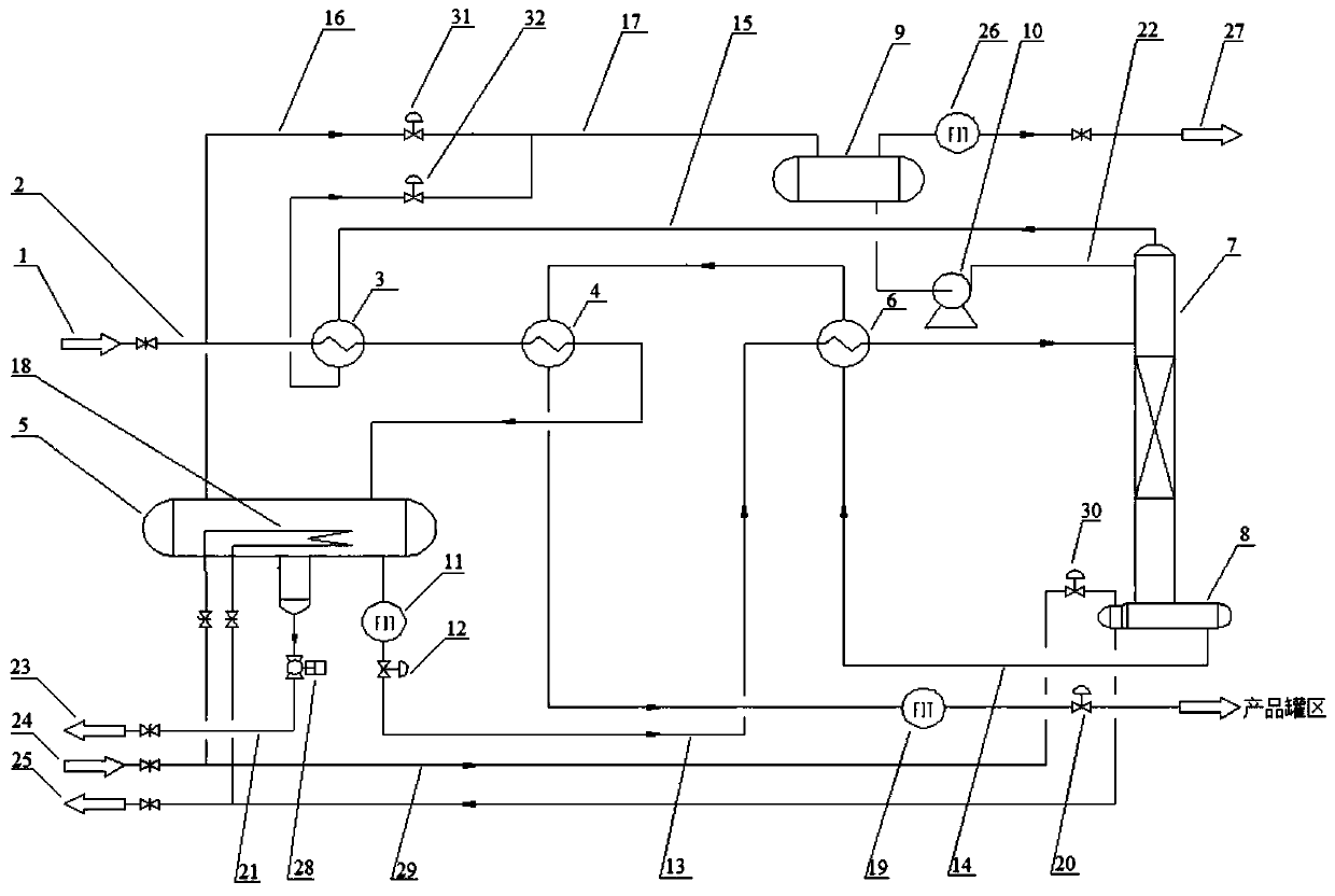
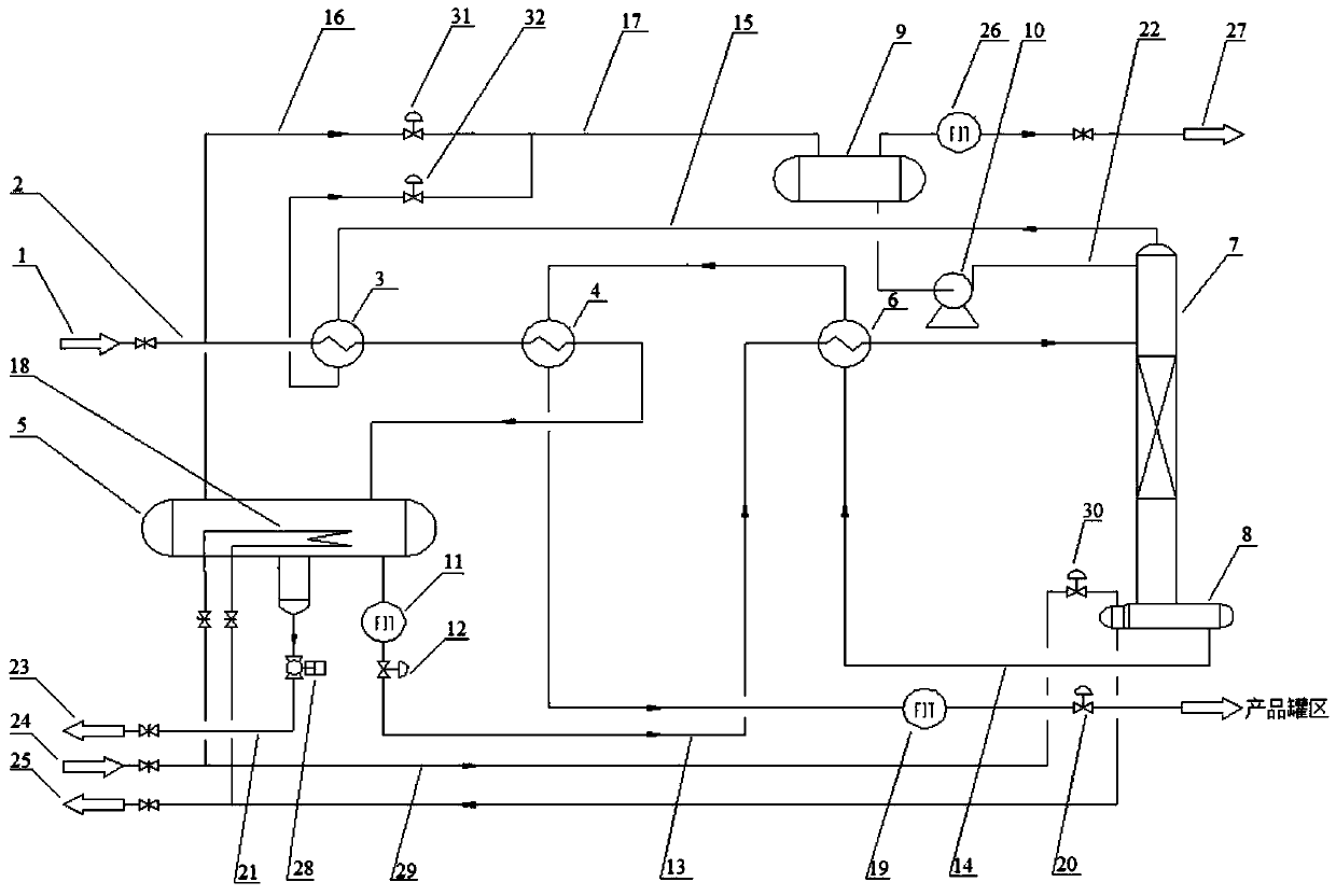
[0034] A low-temperature condensate treatment process of a deoiling and dehydration device in a natural gas treatment plant, comprising the following steps:

[0035] Step 1, the low-temperature condensate 1 is preheated by the non-condensable gas at the top of the condensate stabilization tower 7 in the first-stage gas-liquid heat exchanger 3, and the temperature of the low-temperature condensate 1 increases, and the non-condensable gas at the top of the tower undergoes low-temperature condensation at the same time. Liquid 1 cools down and the temperature decreases;

[0036] Step 2, step 1. The preheated low-temperature condensate 1 is preheated for the second time by the high-temperature stable condensate in the secondary gas-liquid heat exchanger 4, and the temperature rises to 29°C;

[0037] Step 3., the low-temperature condensate 1 after the secondary preheating is separated into gas phase gas, alcohol-containing water and unstabilized condensate oil through the three-phas...

Embodiment 2

[0052] On the basis of Example 1, the temperature of the low-temperature condensate is -15°C, the pressure is 5.5MPa, and the composition is C 1 ~C 11 + , water and methanol, wherein the water content is 16% (mol), the methanol molar content is 19% (mol), C 6 + The content is 46.44% (mol), C 1 ~C 5 The non-condensable gas content was 18.56% (mol).

[0053] The non-condensable gas at the top of the described condensate stabilization tower 7 has a temperature of 45 ° C and a pressure of 0.4 MPa, and the composition is C 1 ~C 11 + and saturated water, in which the saturated water content is 4.92% (mol), C 1 ~C 5 The content is 93.62% (mol), C 6 + The content was 1.46% (mol).

[0054] The preheating and cooling described in step 1 utilizes the heat of the non-condensable gas at the top of the tower and the cooling capacity of the low-temperature condensate 1 at the same time. 45°C is lowered to -5°C; the heating and first cooling described in step ⑤ utilize the coolin...

Embodiment 3

[0059] On the basis of Example 1, the non-condensable gas at the top of the tower described in step ⑥ is mixed with the gas-phase gas of the three-phase separator. Since the condensed liquid in the two is re-equilibrated with gas and liquid, part of the condensed liquid evaporates and absorbs heat, resulting in a temperature drop. , so that the temperature of the mixed gas is lower than the respective temperatures of the non-condensable gas at the top of the tower and the gas phase of the three-phase separator before mixing. When the mixed gas enters the low temperature gas-liquid separator 9 for gas-liquid separation, it needs to be carried out at a low temperature of -10°C to -20°C to ensure that the hydrocarbon dew point of the mixed gas meets the requirements of the fuel gas, and the liquid returns to the top of the tower.

[0060] The stable condensate described in step 5. is heated in the reboiler 8 by the high-temperature heat-conducting oil 24 to form a reboiler, and th...


PUM


Abstract

The invention discloses a low-temperature condensate treatment process for a natural gas treatment plant deoiling and dewatering device. The process includes the following steps that 1, the temperature is increased to 29 DEG C after low-temperature condensate is preheated twice; 2, the low-temperature condensate is separated into gas-phase gas, alcohol-containing water and unstable gas condensate through a three-phase separator; 3, the alcohol-containing water is output to a methyl alcohol recycling device; 4, the unstable gas condensate enters a gas condensate stabilizing tower after being preheated and is heated to 142 DEG C at the tower bottom with conduction oil after being stabilized, the saturated vapor pressure reaches 70 kPa, the temperature is decreased to 40 DEG C after cooling is performed twice, and the stabilized gas condensate is output to a product tank field; 5, the gas-phase gas is mixed with tower top noncondensable gas to generate phase-change cooling, the temperature of the mixed gas is reduced to -10 DEG C, the mixed gas is subjected to low-temperature gas-liquid separation, the hydrocarbon dew point of fuel gas meets the quality requirement, and a liquid phase flows back to the top of the stabilizing tower. The invention further provides a device for implementing the process. Low-temperature separation of mixed gas is achieved under the condition that no external cold supply source is available, and thus investment is reduced; the requirement for cooling high-temperature gas condensate is met under the condition that an air cooler is omitted; besides, the energy of heat flow is reasonably utilized.

Description

technical field [0001] The invention designs a low-temperature condensate treatment process of a deoiling and dehydration device in a natural gas treatment plant, and a device for implementing the process. Background technique [0002] The low-temperature condensate of the de-oiling and dehydration unit of the natural gas treatment plant comes from the low-temperature gas-liquid separator of the unit. The de-oiling and dehydrating unit adopts the low-temperature condensation and separation process of propane refrigeration, which meets the requirements of simultaneous de-oiling and dehydration. After the raw natural gas is processed by the deoiling and dehydration device, the water dew point and hydrocarbon dew point of the product natural gas meet the requirements of the national standard "Natural Gas" GB 17820. The cryogenic condensate separated at low temperature contains water, unstabilized condensate, methanol and dissolved natural gas. . In the low temperature conditio...

Claims


Application Information

Patent Timeline
Patent Type & Authority Patents(China)
IPC IPC(8): C10L3/10
CPCC10L3/10C10L3/106
Inventor 刘子兵粱璇玑李京子赵玉君韩万龙葛涛郄海霞李亚萍杨充
Owner XIAN CHANGQING TECH ENG
Why Eureka
Try Eureka