Clutch cover assembly and friction clutch

A friction clutch and clutch cover technology, applied in the field of vehicles, can solve the problems of broken transmission plates, increased friction, wear and corrosion of transmission plates, etc., to achieve the effect of being conducive to stable support

Pending Publication Date: 2021-10-22
SCHAEFFLER TECH AG & CO KG
View PDF0 Cites 0 Cited by
  • Summary
  • Abstract
  • Description
  • Claims
  • Application Information

AI Technical Summary

Problems solved by technology

However, the increase in the number of stacked transmission plates will also increase the friction, wear and corrosion, which may lead to the fracture of the transmission plates

Method used


Image

  • Clutch cover assembly and friction clutch
  • Clutch cover assembly and friction clutch

Examples


Embodiment Construction

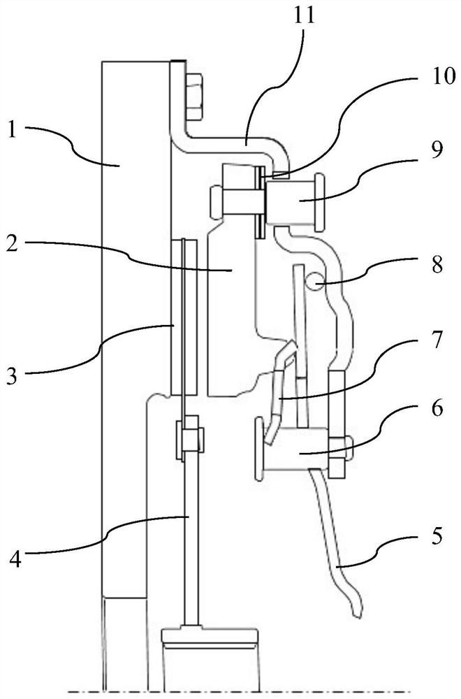
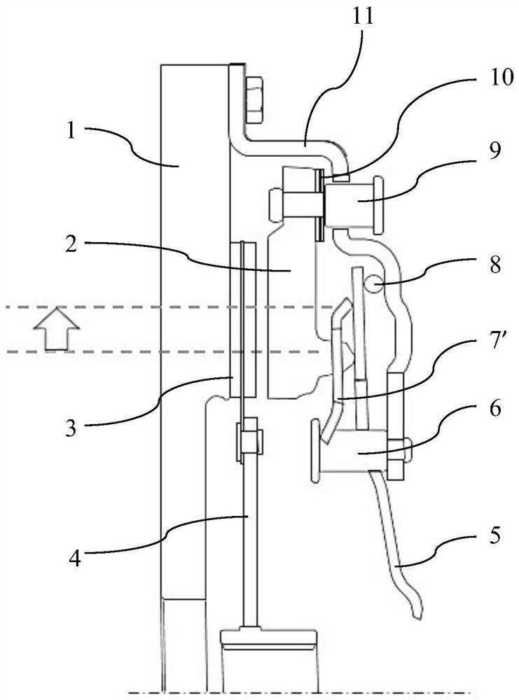
[0025] figure 1 A schematic diagram of a friction clutch according to a preferred embodiment is shown. The friction clutch is used, for example, to transmit torque output from the internal combustion engine in the vehicle to the transmission. The friction clutch is designed here as a normally open friction clutch. The friction clutch has a pairing plate 1, a friction disk 3, and a clutch cap assembly that is arranged in the same axis of rotation, wherein a friction liner is provided on both sides of the axial side of the friction disk 3. Clutch cover assembly includes clutch cover 11, pressure plate 2, and lever spring 5

[0026] The clutch cover 11 and the pairing plate 1 are connected by a bolted outer end. The clutch cover 11 is closed, whereby the clutch cover 11 and the pairing plate 1 constitute a space for accommodating the friction disc 3 and the pressure plate 2. The pairing plate 1 can be connected to an internal combustion engine crank, to transfer the torque of the in...


PUM


Abstract

The invention relates to a clutch cover assembly and a friction clutch. The clutch cover assembly comprises a clutch cover (11), a pressure plate (2) and a lever spring (5); the pressure plate (2) can rotate together with the clutch cover (1) about a common axis of rotation; and the lever spring (5) is located between the clutch cover (11) and the pressure plate (2) and can apply an actuating force to the pressure plate (2) by means of the clutch cover (11) as a lever fulcrum such that the pressure plate (2) can move axially relative to the clutch cover (11); wherein the clutch cover assembly further comprises an auxiliary spring (7) which is supported by one end thereof directly or indirectly on the clutch cover (11) and by the other end thereof on the lever spring (5), such that the auxiliary spring (7) provides a force pressing the lever spring (5) against the clutch cover (11). The friction clutch comprises the clutch cover assembly.

Description

Technical field [0001] The present invention relates to the field of vehicle technology. In particular, the present invention relates to a clutch cap assembly and a friction clutch including such a clutch cap assembly. Background technique [0002] In the friction clutch for motor vehicles, the clutch cover, a diaphragm spring, a pressure plate, a friction plate, and a pair of sheets are typically arranged in the axial direction. The clutch cover is generally configured to rotationally symmetrically coupled with a plate-resistant to the plate. The pressure plate and the clutch cover are connected by a plurality of stacked transmission sheets along the circumferential distribution, and each set of stacked transmission sheets are fixed to the pressure plate through a longitudinal end and by another longitudinal end, for example, on the clutch cover, by This pressure plate and the clutch cover can rotate around the common axis of rotation. The pressure plate can be performed relativ...

Claims


Application Information

Patent Timeline
Patent Type & Authority Applications(China)
IPC IPC(8): F16D13/58F16D13/68F16D13/71
CPCF16D13/583F16D13/585F16D13/71F16D13/68F16D2013/586F16D2013/588
Inventor 范意中
Owner SCHAEFFLER TECH AG & CO KG
Why Eureka
Try Eureka