Diverter valve integrated with waterway switch, waterway control method and cleaning waterway

A technology integrating water circuit and diverter valve, applied in valve details, multi-port valve, valve device and other directions, can solve the problems of occupying system control resources, reducing system stability, increasing system control burden, etc., to simplify control methods and reduce costs. Effect

Pending Publication Date: 2021-10-22
湖南麦格米特电气技术有限公司
View PDF0 Cites 0 Cited by
  • Summary
  • Abstract
  • Description
  • Claims
  • Application Information

AI Technical Summary

Problems solved by technology

[0002] In the existing intelligent toilet cleaning waterway, the function of the waterway switch is realized by the solenoid valve as an independent component. The solenoid valve component controls the on-off of the waterway through the structure of the electromagnetic switch and the pilot valve, and is used as an independent component to clean the waterway system. In the system, there are independent product cost requirements and system control requirements, so the product design input cost, production and maintenance costs are greatly increased, and the burden of system control is increased. A separate control command interface needs to be added, which occupies system control resources and reduces system stability. sex
[0003] And in the existing smart toilet cleaning waterway, such as figure 1 As shown, the solenoid valve with waterway switch function needs to be at the front end of the cleaning waterway, and the switch operation at the front end of the waterway will inevitably cause a delay in the flushing switch effect at the end of the waterway, and the structure of the pilot valve itself is not sensitive enough, so the existing solenoid valve type There is an obvious delay in the waterway switch, which can easily cause users to experience poor experience when using the cleaning function.

Method used


Image

  • Diverter valve integrated with waterway switch, waterway control method and cleaning waterway
  • Diverter valve integrated with waterway switch, waterway control method and cleaning waterway
  • Diverter valve integrated with waterway switch, waterway control method and cleaning waterway

Examples


Embodiment

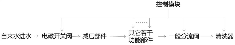
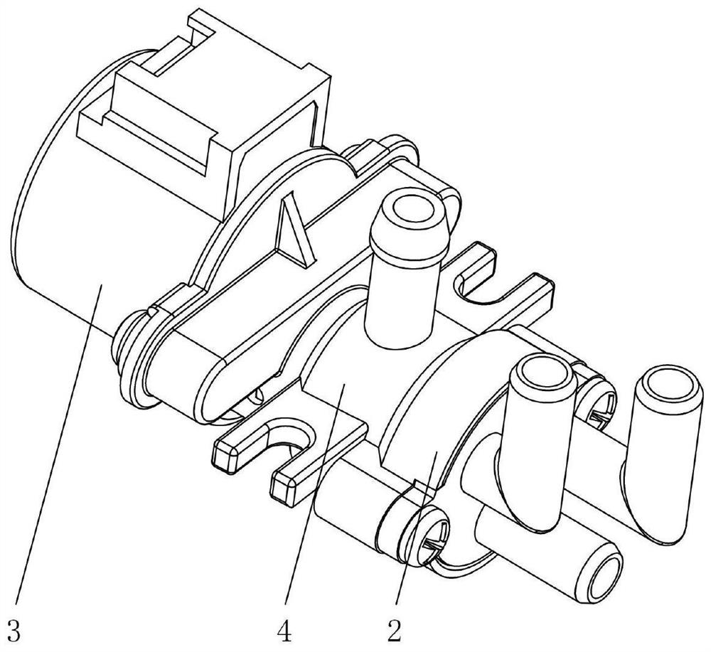
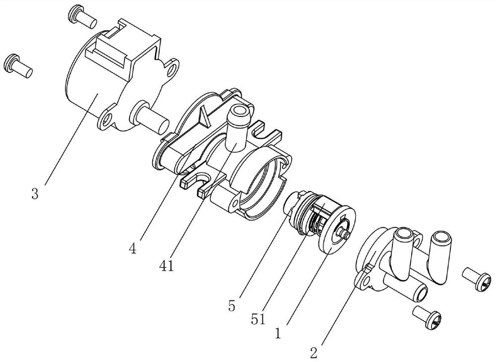
[0035] Such as figure 1 , figure 2 , Figure 5 and Figure 6 As shown, the diverter valve of the integrated waterway switch of this embodiment includes a valve core 1, a valve seat 2 and a rotary drive member 3, and the end surface of the valve seat 2 in contact with the valve core 1 is provided with a plurality of valves communicating with each water passage. The water outlet 21, the end surface of the valve core 1 in contact with the valve seat 2 is provided with a water hole 11 communicating with the water inlet 41, the rotary drive 3 drives the valve core 1 to rotate relative to the valve seat 2, each water outlet 21 and the water outlet The holes 11 are distributed on a ring centered on the relative center of rotation. During the rotation process, the water holes 11 can be connected with each water outlet 21, so that the water flow entered by the water inlet 41 is output to each water channel, realizing use water.

[0036] Different from the existing conventional div...


PUM


Abstract

The invention discloses a diverter valve integrated with a waterway switch, a waterway control method and a cleaning waterway. The diverter valve comprises a valve element, a valve seat and a rotary driving part, a plurality of water outlets communicated with water use channels are formed in the end face, making contact with the valve element, of the valve seat, water passing holes communicated with a water inlet are formed in the end face, making contact with the valve seat, of the valve element, and the rotary driving part drives the valve element to rotate relative to the valve seat; and the water outlets and the water passing holes are distributed in a circular ring with the relative rotation center as the circle center, a blocking piece used for blocking the water inlet when the valve element rotates to the set position where the water passing holes and the water outlets are not communicated is further included, and the blocking piece and the valve element rotate synchronously. The diverter valve has the advantages of being simple in structure, flexible and convenient to adjust, integrated in function and the like; the waterway control method has the advantages of being high in adjusting sensitivity, eliminating the delay phenomenon, optimizing the use feeling of a user and the like; and the cleaning waterway has the advantages of being high in stability, obvious in cost optimization and the like.

Description

technical field [0001] The invention relates to the technical field of valve body structure, in particular to a diverter valve with an integrated waterway switch, a waterway control method and a waterway cleaning method. Background technique [0002] In the existing intelligent toilet cleaning waterway, the function of the waterway switch is realized by the solenoid valve as an independent component. The solenoid valve component controls the on-off of the waterway through the structure of the electromagnetic switch and the pilot valve, and is used as an independent component to clean the waterway system. In the system, there are independent product cost requirements and system control requirements, so the product design input cost, production and maintenance costs are greatly increased, and the burden of system control is increased. A separate control command interface needs to be added, which occupies system control resources and reduces system stability. sex. [0003] And...

Claims


Application Information

Patent Timeline
IPC IPC(8): F16K11/074F16K27/04F16K31/04
CPCF16K11/074F16K27/045F16K31/041
Inventor 徐波王林江
Owner 湖南麦格米特电气技术有限公司
Why Eureka
Try Eureka