
A new type of pressure-retaining valve

A pressure-holding valve, a new type of technology, applied in the direction of lifting valve, valve device, valve details, etc., can solve the problems of bottle gas quality decline, large piston contact area, loose gasket, etc., to improve practicability and ensure movement accuracy Effect

Active Publication Date: 2022-08-02
宁波三安制阀有限公司
View PDF6 Cites 0 Cited by
  • Summary
  • Abstract
  • Description
  • Claims
  • Application Information

AI Technical Summary

Problems solved by technology

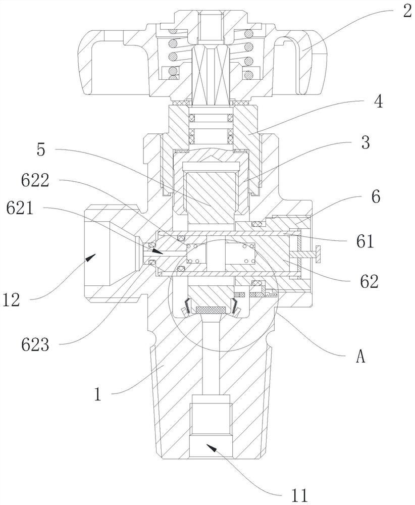
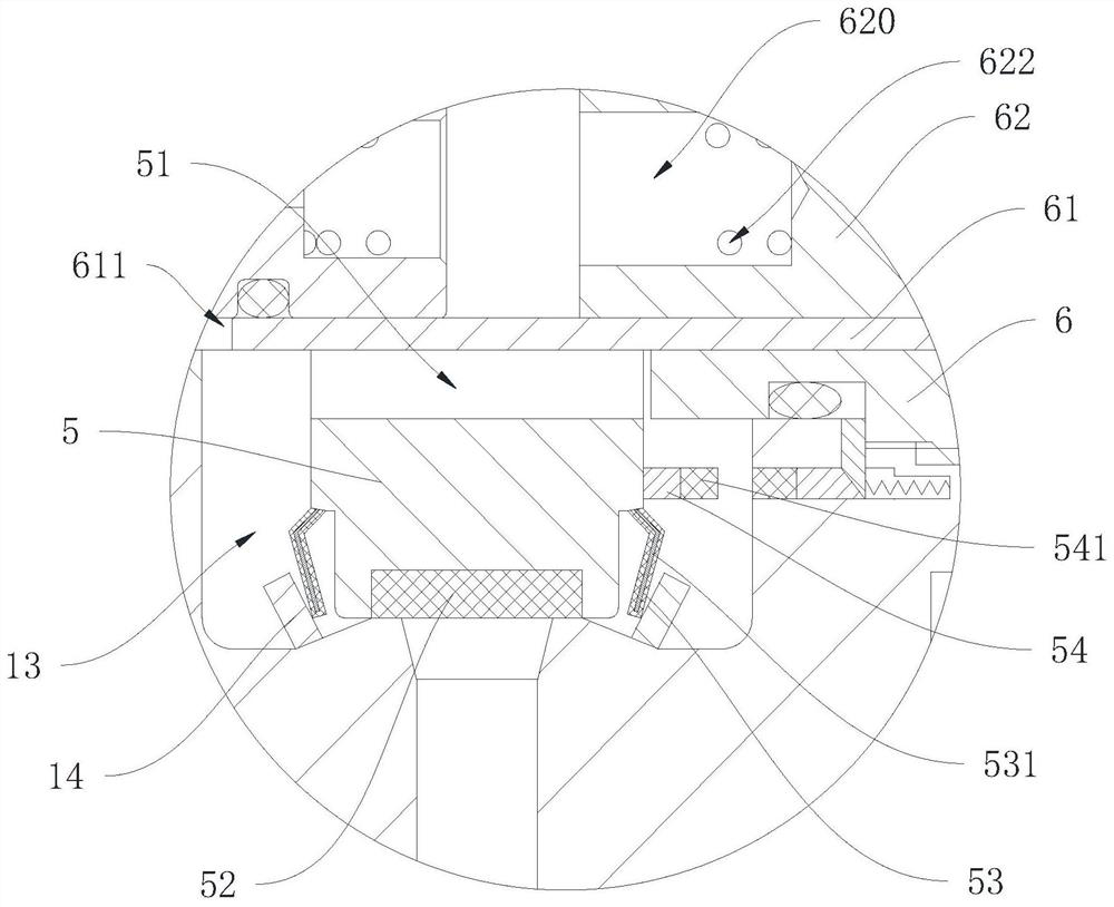
[0004] (1) The gasket in the piston of the pressure maintaining valve in the prior art is compressed on the piston, and the gasket at the bottom of the piston is in sealing contact with the valve body to form a valve. Since the gasket material is non-metallic, the contact area with the piston is large. And when the gasket is sealed with the air inlet, the mouth is located in the center of the gasket. Therefore, the gasket is easy to cause deformation at the bottom of the piston when it is pressed, resulting in the loosening of the gasket at the bottom of the piston, and the valve is working many times. During the opening and closing process, the sealing performance between the gasket and the air inlet may be reduced or the gasket in the piston may be separated, which will affect the normal operation of the pressure maintaining valve.
[0005] (2) In order to ensure the purity of the gas in the bottle, attention should be paid to the sealing of the air inlet when the screw sleeve is installed, but the staff often ignore this point when loading and unloading the screw sleeve, which will cause the quality of the gas in the bottle to decline, and the staff will It is difficult to determine whether the first valve in the bottle is completely closed, which is time-consuming and laborious
[0006] (3) In the prior art, the opening and closing of the first valve is controlled by the piston, but when the first valve is opened, the gas outflow speed is constant, and the speed of the gas outflow from the gas outlet cannot be controlled, so it is difficult to meet the flexibility requirements

Method used


Image

  • A new type of pressure-retaining valve
  • A new type of pressure-retaining valve
  • A new type of pressure-retaining valve

Examples


Embodiment Construction

[0029]The present application will be further described below with reference to the specific embodiments. It should be noted that, under the premise of no conflict, the embodiments or technical features described below can be arbitrarily combined to form new embodiments.

[0030] In the description of this application, it should be noted that, for orientation words, such as the terms "center", "upper", "lower", "front", "rear", "vertical", "horizontal", "inside" ”, “outer” and the like indicate the orientation and positional relationship based on the orientation or positional relationship shown in the accompanying drawings, which are only for the convenience of describing the present application and simplifying the description, rather than indicating or implying that the device or element referred to must have a specific orientation , is constructed and operated in a specific orientation, and should not be construed as limiting the specific protection scope of the present appli...


PUM


Abstract

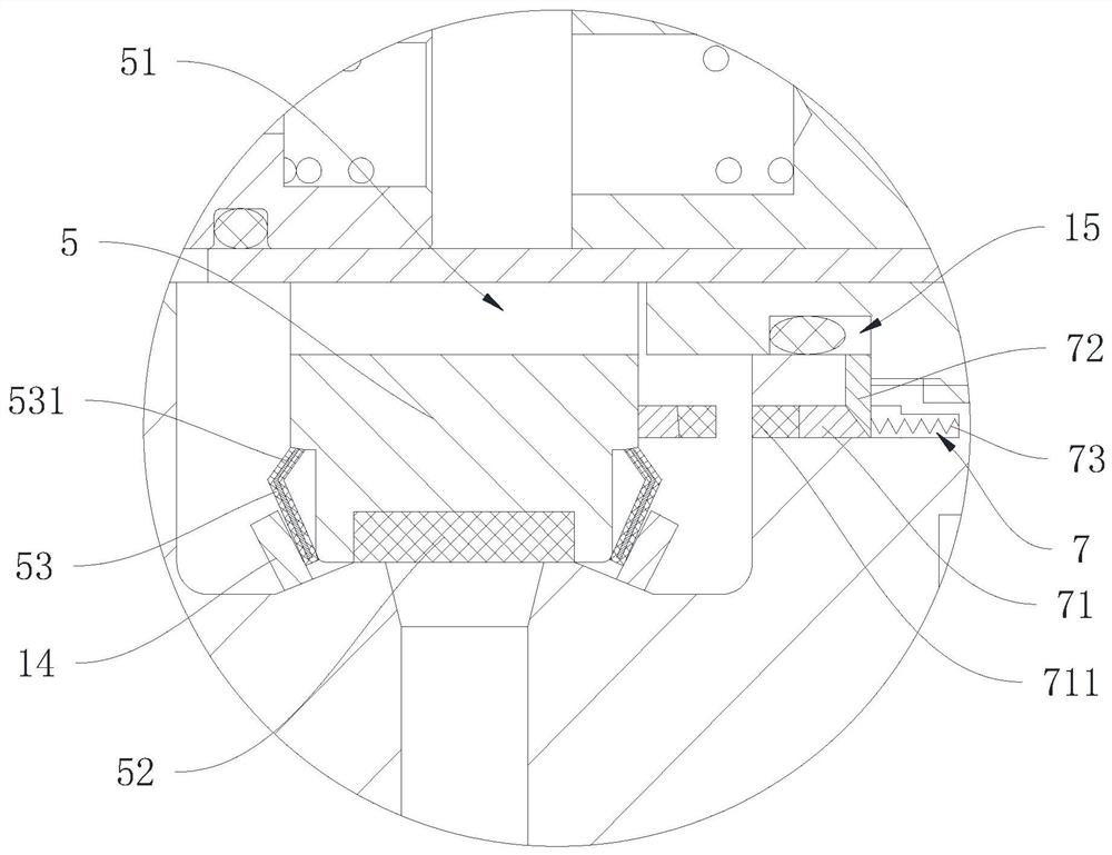
The application discloses a novel pressure maintaining valve, comprising: a valve body, an air inlet and an air outlet are formed on the valve body, and a gas cylinder release channel is formed in the valve body; a valve assembly is arranged in the valve body, and the valve assembly includes a valve stem and the piston, the piston is provided with a through groove, and the bottom end of the piston is provided with a sealing gasket; the screw sleeve is threadedly connected to the valve body, the screw sleeve passes through the through groove and is opposite to the air outlet, and the screw sleeve is provided with a bushing, a guide sleeve and a first spring, the guide sleeve is provided with a sealing ring, the first spring is pressed against the guide sleeve, the bushing covers the guide sleeve, and the guide sleeve is provided with a guide opening, and the guide opening adjusts the moving position through the movement of the sleeve; and The limiting part is arranged at the air outlet of the valve body, the bottom of the piston is provided with a plurality of support arms, and the limiting part can force the support arms to press against the bottom of the piston. The application can ensure the tightness of the pressure-holding valve after long-term use, improve the gas tightness in the pressure-holding valve during installation, and can flexibly adjust the gas outflow rate when the gas is released, so as to flexibly adapt to various application scenarios .

Description

technical field [0001] The present application relates to the technical field of valves, in particular to a novel pressure maintaining valve. Background technique [0002] The pressure-retaining valve is a valve that can ensure that the gas in the gas cylinder is pure and has a certain pressure. The valve body in the prior art is equipped with a piston, and the sealing gasket at the lower end of the piston is in sealing contact with the valve body; the piston is connected with the lower part of the valve stem, the upper part of the valve stem is provided with a hand wheel, the guide sleeve is placed in the screw sleeve, and the screw sleeve drives the guide sleeve to pass through. Passing between the valve body and the piston, it is connected with the valve body outlet, the guide sleeve is pressed against the valve body under the action of the guide sleeve spring, and the upper seal of the guide sleeve contacts the valve body to form a valve. [0003] However, the new gas p...

Claims


Application Information

Patent Timeline
Patent Type & Authority Patents(China)
IPC IPC(8): F17C13/04F16K1/02F16K1/36F16K1/32F16K27/02F16K31/60F16K31/50
CPCF17C13/04F16K1/02F16K1/36F16K1/32F16K27/02F16K31/60F16K31/50
Inventor 仇领光孙科鲍凯
Owner 宁波三安制阀有限公司
Learn More