Automatic feeding equipment for symmetrical positions of paired workpieces

An automatic feeding and symmetrical technology, applied in the direction of conveyor objects, conveyor control devices, conveyors, etc., can solve the problems of unreasonable line laying and error superposition caused by many driving components

Active Publication Date: 2020-03-24
SUZHOU ZHIRUI PHOTOELECTRIC MATERIAL TECH CO LTD
View PDF5 Cites 1 Cited by
  • Summary
  • Abstract
  • Description
  • Claims
  • Application Information

AI Technical Summary

Problems solved by technology

[0005] The technical problem to be solved by the present invention is: to provide a paired Automatic feeding equipment for the symmetrical position of the workpiece

Method used


Image

  • Automatic feeding equipment for symmetrical positions of paired workpieces
  • Automatic feeding equipment for symmetrical positions of paired workpieces
  • Automatic feeding equipment for symmetrical positions of paired workpieces

Examples


Embodiment 1

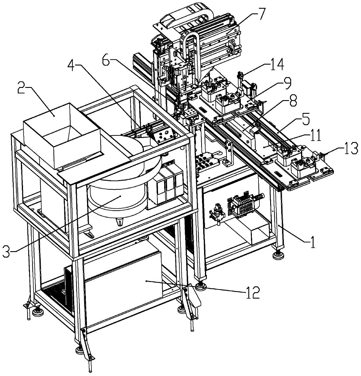
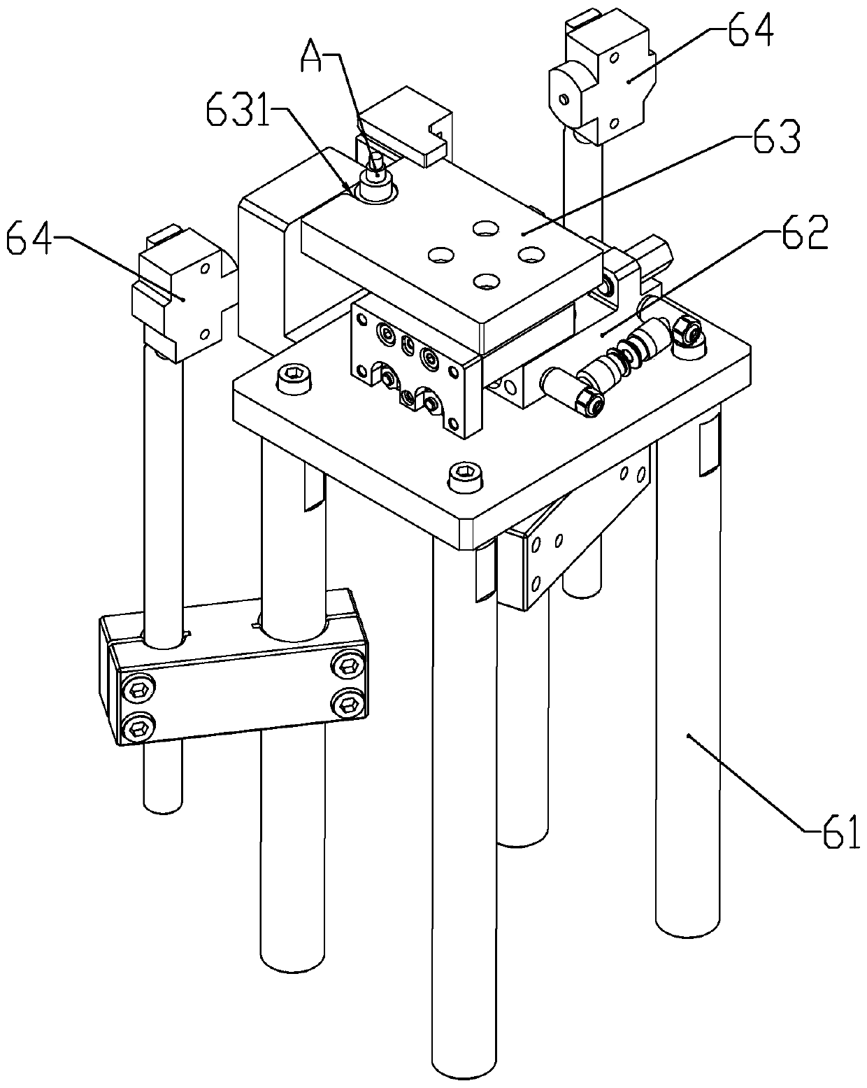
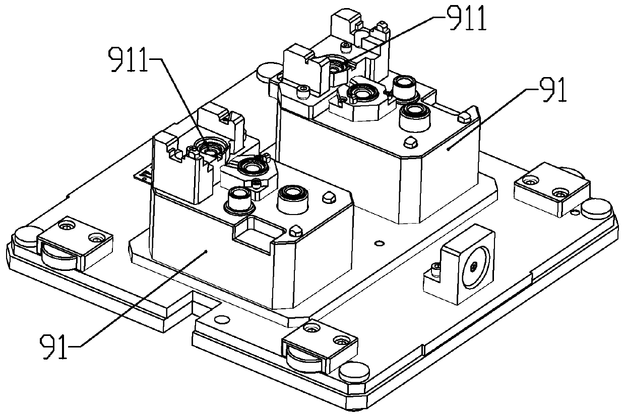
[0045] according to Figure 1 to Figure 12 As shown, a symmetrical position automatic feeding device for a pair of workpieces described in this embodiment includes a chassis 1, a hopper 2, a vibrating plate 3 installed on one side of the hopper for arranging the parts in sequence, and a vibrating plate installed on the The outlet of the vibrating plate is used to transport the feed rail 4 of the parts and the assembly line 5 installed on the chassis; the assembly line is provided with a carrier 9; the chassis is fixedly connected with a mounting plate 11; the mounting plate A material receiving part 6, a transplanting mechanism 7 for installing parts from the material receiving part on the carrier, and a positioning mechanism 8 for positioning the carrier are respectively installed on the upper part; the transplanting mechanism has no displacement along the direction of the assembly line and each The trajectory of the secondary movement is the same; the carrier moves to the su...

Embodiment 2

[0065] This embodiment makes the following improvements on the basis of Embodiment 1: no contact switch is installed on the transplanting mechanism; the third sensor only detects Components. In the initial state, the third sensor detects that there is no part in the corresponding part installation hole. After the transplanting mechanism grabs the part from the material receiving part, it controls the moving assembly to remain fixed. After the transplanting mechanism installs the part into the part installation hole , if there is a part detected by the third sensor, then the mobile assembly is controlled to work so that another part mounting hole is located at the third sensor, and at this time, the third sensor detects that there is no part in the part mounting hole, then repeat the above steps, and the rest of the steps Same as Embodiment 1; in the above steps, when the moving component moves the part installation hole located at the front end of the assembly line to the inst...


PUM


Abstract

The invention belongs to the field of machining and particularly relates to automatic feeding equipment for symmetrical positions of paired workpieces. The equipment comprises a bottom frame, a hopper, a vibrating disk, a conveying rail which is mounted at an outlet of the vibrating disk and used for conveying parts, and an assembly line mounted on the bottom frame, wherein a carrier is arranged on the assembly line, a mounting plate is fixedly connected with the bottom frame, the mounting plate is provided with a material receiving part, a transplanting mechanism used for mounting parts ontothe carrier from the material receiving part and a positioning mechanism used for positioning the carrier, the transplanting mechanism has no displacement in the direction of the assembly line, and the movement tracks of the transplanting mechanism are the same all the time. The equipment is advantaged in that the positioning mechanism is arranged so that two part mounting holes in the carrier move to the same mounting position by several times, moving tracks of the transplanting mechanism are the same, and moving precision of a pneumatic clamping jaw during part clamping is kept, through a structural form, moving precision of the positioning mechanism driving the carrier to move can be kept consistent, and errors are reduced.

Description

technical field [0001] The invention belongs to the field of mechanical processing, and in particular relates to an automatic feeding device for symmetrical positions of a pair of workpieces. Background technique [0002] In the existing machining process, there are often symmetrically arranged workpieces, which need to be assembled after mold splitting and symmetrical processing. However, some parts often need to be installed on the workpiece for the next step, such as the installation of parts on the car door and the symmetrical multi-way valve. The position of the spool installation, etc.; after the parts are processed in batches, there are a large number of parts. Usually, the parts are installed on the workpiece manually or by manipulators. When installing by workers, because the workpiece is a symmetrical piece, the installation is cumbersome; After the workpiece is installed on the corresponding carrier, the two parts are respectively installed on a pair of workpieces...

Claims


Application Information

Patent Timeline
IPC IPC(8): B65G37/02B65G47/22B65G47/88B65G43/08B65G47/14B65G47/90
CPCB65G37/02B65G43/08B65G47/1421B65G47/22B65G47/8815B65G47/901B65G2203/042
Inventor 武立宝
Owner SUZHOU ZHIRUI PHOTOELECTRIC MATERIAL TECH CO LTD
Why Eureka
Try Eureka