Dustproof device for ventilation of closed cooling tower
A technology of closed cooling towers and dust-proof devices, which is applied in the direction of water shower coolers, damage protection, direct contact heat exchangers, etc., which can solve the problems of inconvenient cleaning of dust, heating of pipes, and inconvenient ventilation, etc., and achieve easy cleaning of dust Effect
- Summary
- Abstract
- Description
- Claims
- Application Information
AI Technical Summary
Problems solved by technology
Method used
Image

Examples
Embodiment 1
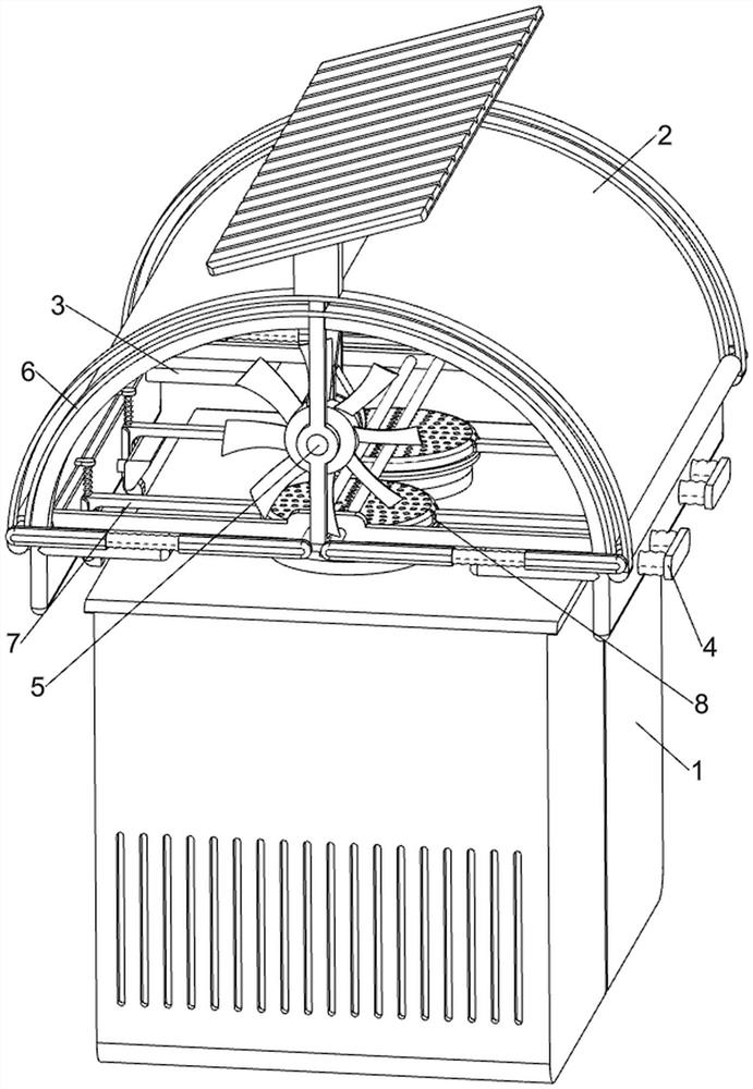
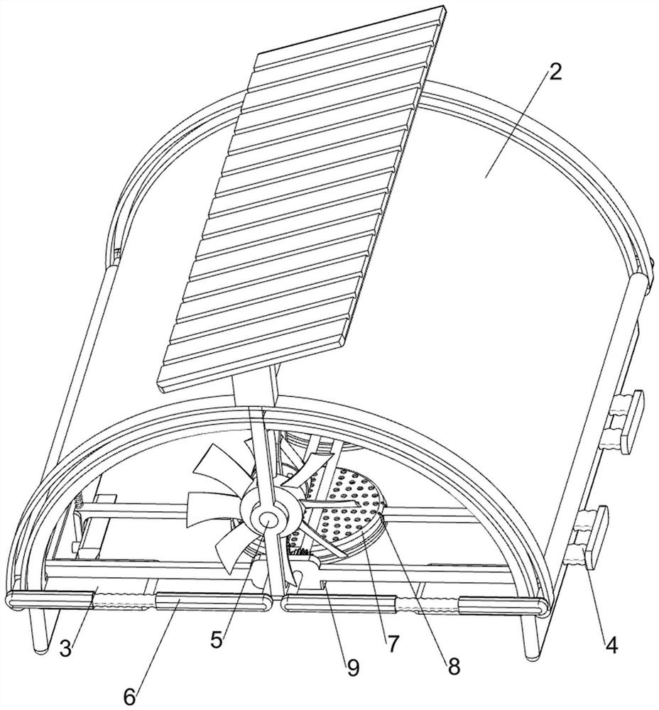
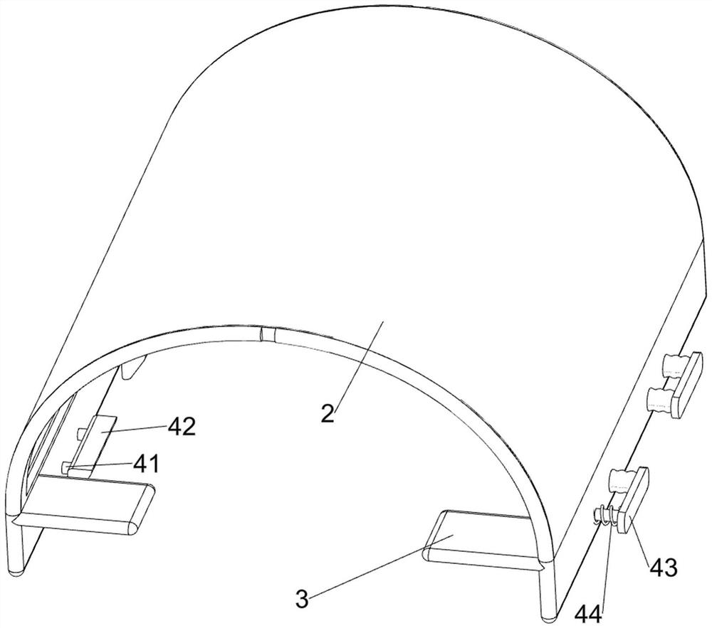
[0030] A dust-proof device for fluid cooling tower ventilation, such as figure 1 , figure 2 , image 3 , Figure 4 and Figure 7 As shown, it includes a closed cooling tower 1, a curved plate 2, a clamping plate 3, a clamping mechanism 4, and a ventilation mechanism 5. A curved plate 2 is placed on the upper part of the closed cooling tower 1, and the inner side of the curved plate 2 is symmetrically arranged. There are two clamping plates 3, and a clamping mechanism 4 is provided on the outside of the arc plate 2, and the clamping mechanism 4 cooperates with the closed cooling tower 1, and a ventilation mechanism 5 is provided on the arc plate 2.
[0031] The clamping mechanism 4 includes a connecting rod 41, a block 42, a connecting block 43 and a first spring 44. Two pairs of connecting rods 41 are arranged in a left and right symmetrical sliding manner on the outside of the arc-shaped plate 2, and each pair of connecting rods 41 insides are provided with two pairs of c...
Embodiment 2
[0036] On the basis of Example 1, such as Figure 5 , Figure 6 , Figure 8 , Figure 9 and Figure 10 As shown, a dust removal assembly 6 is also included, and the dust removal assembly 6 includes an arc guide rail 61, an engaging rod 62, a first rotating shaft 63, a rotating rod 64, a first guide rod 65, a second spring 66, a roller 67, and a full gear 68 , rack 69, planetary gear 610 and the 3rd spring 611, arc-shaped plate 2 upper part is provided with arc-shaped guide rail 61 symmetrically front and back, and arc-shaped plate 2 inside lower part is provided with connecting rod 62 symmetrically before and after, and connecting rod 62 is symmetrically rotated A first rotating shaft 63 is provided, and the left and right symmetrical rotation type of the arc guide rail 61 outside is provided with a cylinder 67, and the outside of the first rotating shaft 63 is equipped with a rotating rod 64 symmetrically before and after, and the inside of the cylinder 67 is also equipped...
PUM
 Abstract
Description
Claims
Application Information
 - R&D
- Intellectual Property
- Life Sciences
- Materials
- Tech Scout
- Unparalleled Data Quality
- Higher Quality Content
- 60% Fewer Hallucinations
Browse by: Latest US Patents, China's latest patents, Technical Efficacy Thesaurus, Application Domain, Technology Topic, Popular Technical Reports.
© 2025 PatSnap. All rights reserved.Legal|Privacy policy|Modern Slavery Act Transparency Statement|Sitemap|About US| Contact US: help@patsnap.com