Imaging module and method for assembling the same

A technology of imaging module and assembly method, applied in installation, image communication, television, etc., capable of solving problems such as generation of fine dust, low yield rate of imaging module 100, and reduction of imaging quality of image sensor 15

Inactive Publication Date: 2014-03-26
HONG FU JIN PRECISION IND (SHENZHEN) CO LTD +1
View PDF6 Cites 0 Cited by
  • Summary
  • Abstract
  • Description
  • Claims
  • Application Information

AI Technical Summary

Problems solved by technology

However, in the process of bonding the optical filter 13 to the base 11, it is easy to generate dust in the closed space 16, and the dust will adhere to the optic

Method used


Image

  • Imaging module and method for assembling the same
  • Imaging module and method for assembling the same
  • Imaging module and method for assembling the same

Examples


Embodiment Construction

[0017] The present invention will be further described in detail below in conjunction with the accompanying drawings.

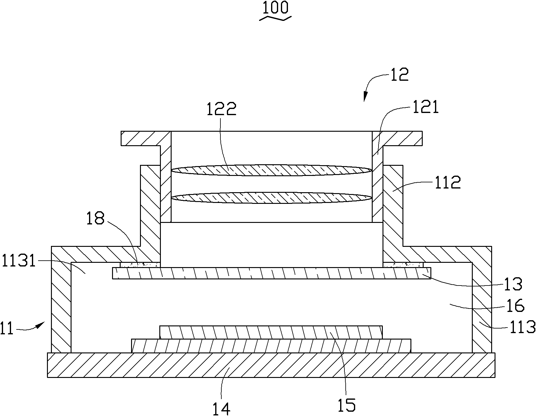
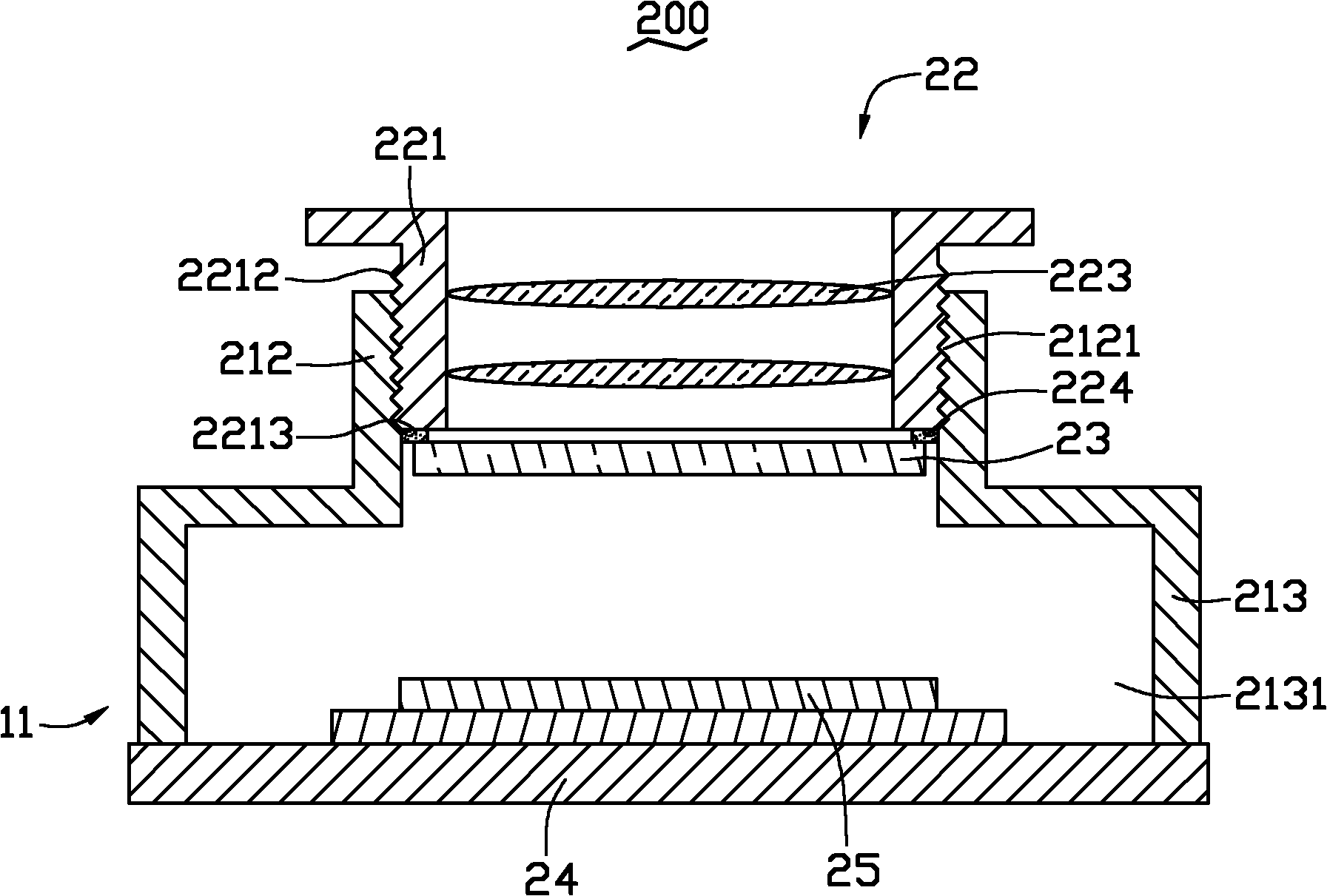
[0018] see figure 2 The imaging module 200 according to the first embodiment of the present invention includes: a base 21 , a lens module 22 , a filter 23 , a substrate 24 and an image sensor 25 electrically connected to the substrate 24 . The image sensor 25 is disposed on the upper surface of the substrate 24 and aligned with the lens module 22 , and incident light passes through the lens module 22 and the filter 23 to the image sensor 25 in sequence.

[0019] The base 21 includes a viewing tube 212 and a base 213 integrally formed with the viewing tube 212 . The viewfinder tube 212 is cylindrical and defines a threaded hole 2121 . The base 213 is rectangular and forms a receiving portion 2131 . The accommodating portion 2131 communicates with the threaded hole 2121 and is roughly a rectangular groove. The substrate 24 is fixedly disposed on the openin...


PUM


Abstract

An imaging module comprises a pedestal, a lens module, an optical filter, a base plate connected to the pedestal, and an image sensor which is electrically connected with the substrate. The pedestal comprises a view finding barrel and a base inside which a receiving portion is formed, wherein the image sensor is accommodated in the receiving portion. The lens module is fastened into the view finding barrel and comprises a lens barrel and at least one lens arranged in the lens barrel. The lens module is provided with an adhesive rubber mass. The optical filter is bonded to the lens module through the adhesive rubber mass. Besides, incident light orderly passes through the lens module and the optical filter to arrive in the image sensor. The imaging module is easy to manufacture and high in yield. The invention also provides a method for assembling the imaging module.

Description

technical field [0001] The invention relates to an imaging module and an assembly method of the imaging module. Background technique [0002] See figure 1 , a conventional imaging module 100 includes a base 11 , a lens module 12 , a filter 13 , a substrate 14 and an image sensor 15 disposed on the surface of the substrate 14 . The base 11 includes a viewing tube 112 and a base 113 , and an accommodating portion 1131 is formed inside the base 113 . The substrate 14 is fixedly connected to the base 11 , and the image sensor 15 is accommodated in the accommodating portion 1131 . The lens module 12 includes a lens barrel 121 and a lens group 122 accommodated in the lens barrel 121 . The lens barrel 121 is screwed to the viewfinder barrel 112 . The filter 13 is disposed under the lens module 12 and is fixedly connected to the base 113 . The incident light passes through the lens module 12 and the filter 13 to the image sensor 15 sequentially. The image sensor 15 is accommoda...

Claims


Application Information

Patent Timeline
IPC IPC(8): G02B7/00G03B17/12H04N5/225
Inventor 邓明育
Owner HONG FU JIN PRECISION IND (SHENZHEN) CO LTD
Why Eureka
Try Eureka