Real-time monitoring equipment for ecological flow discharged by water conservancy and hydropower engineering

A technology of ecological flow, water conservancy and hydropower, which is applied in the direction of liquid/fluid solid measurement, measuring device, measuring capacity, etc., can solve the problems of increasing the rotation speed of the turbine, flow error, etc., and achieve the effect of avoiding backflow

Inactive Publication Date: 2021-10-22
皮玉红
View PDF0 Cites 0 Cited by
  • Summary
  • Abstract
  • Description
  • Claims
  • Application Information

AI Technical Summary

Problems solved by technology

[0003] Based on the inventors' findings above, the existing real-time monitoring equipment for the ecological flow of water conservancy and hydropower projects mainly has the following deficiencies. Sediment, and the sediment mixed in the water will impact the turbine to increase the rotation speed, so that the flow rate detected by the monitoring equipment will have errors.

Method used


Image

  • Real-time monitoring equipment for ecological flow discharged by water conservancy and hydropower engineering
  • Real-time monitoring equipment for ecological flow discharged by water conservancy and hydropower engineering
  • Real-time monitoring equipment for ecological flow discharged by water conservancy and hydropower engineering

Examples


Embodiment 1

[0028] Example 1: Please refer to Figure 1-Figure 6 , the specific embodiments of the present invention are as follows:

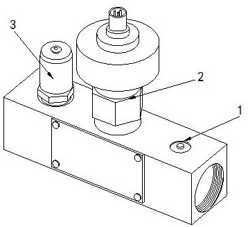
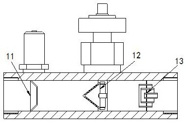
[0029] Its structure includes a main body 1, a data conversion device 2, and a fixed block 3. The data conversion device 2 is arranged in the middle of the top of the main body 1, and the fixed block 3 is located at the top side of the main body 1. The main body 1 includes a collector Block 11, turbine device 12, and rear flow block 13, the collector block 11 is arranged at the front end of the main body 1, the turbine device 12 is located in the middle of the interior of the main body 1, and the rear flow block 13 is arranged at the front of the main body 1 internal backend.

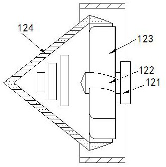
[0030] The turbine device includes a conversion block 121, a rotating shaft 122, blades 123, and a straightening device 124. The conversion block 121 is arranged in the middle of the main body 1, and the rotation shaft 122 is connected to the front end of the conversion block 121. ...

Embodiment 2

[0035] Example 2: Please refer to Figure 7-Figure 9 , the specific embodiments of the present invention are as follows:

[0036] The diversion device a3 includes a diversion block c1, a collecting tank c2, and a flat water tank c3. The diversion block c1 is arranged at the rear end of the rectifying block a1, and there are three collecting tanks c2 arranged horizontally on The side end of the diversion block c1, the flat water tank c3 is connected to the lower end of the collecting tank c2, and the end surface of the collecting tank c2 is arc-shaped, which is beneficial to guide the water flow downward through the collecting tank c2.

[0037] The flat water tank c3 includes a tank body c31, a horizontal piece c32, a through groove c33, and a rear flow tank c34. The tank body c31 is arranged at the lower end of the collecting tank c2. There are three horizontal pieces c32 arranged vertically Inside the tank body c31, the through groove c33 is arranged at the front part of the s...


PUM


Abstract

The invention discloses real-time monitoring equipment for ecological flow discharged by water conservancy and hydropower engineering, which structurally comprises a main body, data conversion equipment and a fixing block, the data conversion equipment is arranged in the middle of the top of the main body, and the fixing block is located at the side end of the top of the main body; the main body comprises a flow collecting block, a turbine device and a back flow block, the back flow block comprises a conversion block, a rotating shaft, blades and a flow rectifying device; the flow rectifying device comprises a flow rectifying block, a water through hole, a flow guiding device and a flow smoothing block; the water through hole comprises a water through groove, a flow guiding port, a partition plate and a flow smoothing plate; and the partition plate comprises a plate body, a sand filtering hole and a sand guiding block. According to the invention, the sediment mixed in water flow is guided backwards through the water passing grooves in the rectification blocks, the situation that the sediment flows backwards along with the water flow from the water passing grooves is prevented, the situation that the rotating speed of the rotating shaft is increased due to the fact that the sediment is mixed in the water flow is avoided, and the equipment can accurately monitor the water flow.

Description

technical field [0001] The invention relates to the field of water conservancy and hydropower, in particular to a real-time monitoring device for ecological flow discharged by a water conservancy and hydropower project. Background technique [0002] The monitoring equipment can automatically monitor, store, and remotely transmit the ecological flow data released by water conservancy and hydropower projects in real time, and can also realize real-time dynamic automatic remote supervision of the ecological flow discharged by water conservancy and hydropower projects. During work, the flow test and measurement are completed through pressure and vibration ultrasonic reactions, which is convenient The operator works, and the detection equipment converts the rotational speed into a flow rate through the rotation of the turbine, and then converts the flow rate into a flow rate, so as to achieve the monitoring effect. [0003] Based on the inventors' findings above, the existing rea...

Claims


Application Information

Patent Timeline
Patent Type & Authority Applications(China)
IPC IPC(8): G01F15/10G01F15/12G01F15/18G01F15/00
CPCG01F15/105G01F15/12G01F15/185G01F15/00
Inventor 皮玉红
Owner 皮玉红
Why Eureka
Try Eureka