
Jitter test equipment for small mechanical and electrical products

A technology for electromechanical products and testing equipment, which is applied in the field of jitter testing equipment for small electromechanical products. It can solve the problems of large influence on the surrounding environment, cumbersome operation process, and inconspicuous test results, and achieve small environmental impact, simple operation process, and high test results. obvious effect

Pending Publication Date: 2021-10-22
武汉佳兴高能科技有限公司
View PDF0 Cites 1 Cited by
  • Summary
  • Abstract
  • Description
  • Claims
  • Application Information

AI Technical Summary

Problems solved by technology

[0005] In order to overcome the shortcomings of the existing mechanical and electrical product testing equipment, such as cumbersome operation process, inconspicuous test results, and great influence on the surrounding environment, the technical problem to be solved by the present invention is to provide a device with simple operation process, obvious test results, and good environmental protection. Jitter test equipment for small electromechanical products with less environmental impact

Method used


Image

  • Jitter test equipment for small mechanical and electrical products
  • Jitter test equipment for small mechanical and electrical products
  • Jitter test equipment for small mechanical and electrical products

Examples


Embodiment 1

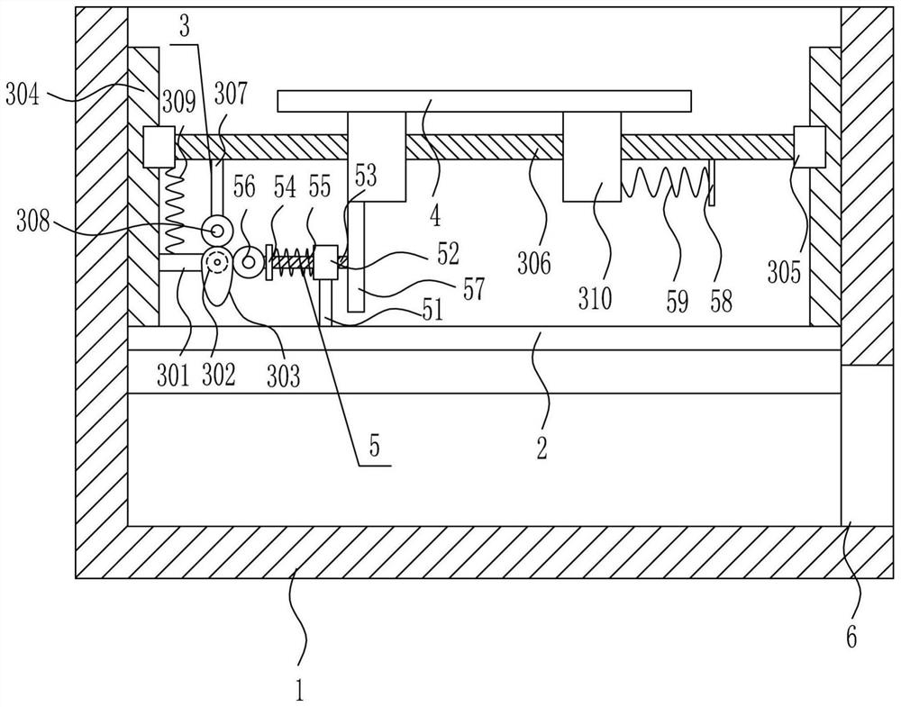
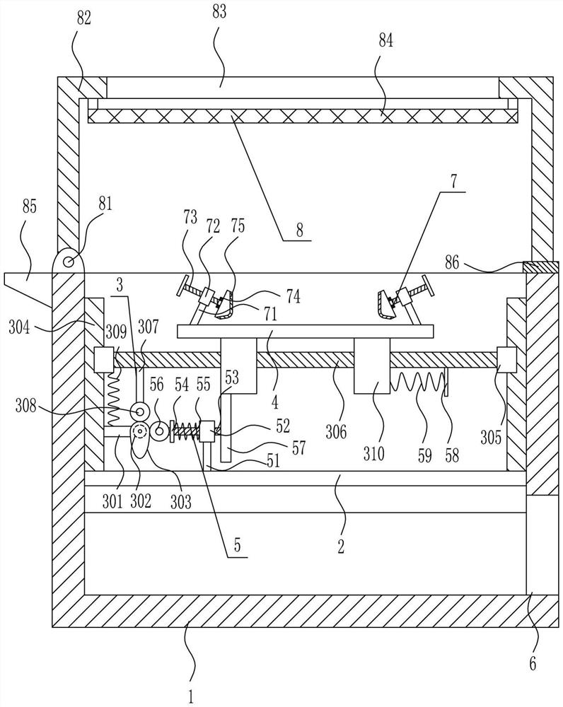
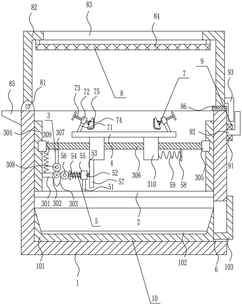
[0029] A jitter test equipment for small electromechanical products, such as Figure 1-3 As shown, it includes a test box 1, a mounting plate 2, a vertical shaking mechanism 3, an operating table 4, and a left and right shaking mechanism 5. The middle part between the left and right side walls of the test box 1 is connected with a mounting plate 2, and the mounting plate 2 is installed There is an up and down shaking mechanism 3, the moving part of the up and down shaking mechanism 3 is connected with an operating table 4, a left and right shaking mechanism 5 is installed on the mounting plate 2, and a first through hole 6 is provided on the right side of the test box 1 bottom.

Embodiment 2

[0031] A jitter test equipment for small electromechanical products, such as Figure 1-3 As shown, it includes a test box 1, a mounting plate 2, a vertical shaking mechanism 3, an operating table 4, and a left and right shaking mechanism 5. The middle part between the left and right side walls of the test box 1 is connected with a mounting plate 2, and the mounting plate 2 is installed There is an up and down shaking mechanism 3, the moving part of the up and down shaking mechanism 3 is connected with an operating table 4, a left and right shaking mechanism 5 is installed on the mounting plate 2, and a first through hole 6 is provided on the right side of the test box 1 bottom.

[0032] The up and down shaking mechanism 3 includes a first pole 301, a motor 302, a cam 303, a slide rail 304, a slide block 305, a first slide bar 306, a second pole 307, a first contact wheel 308, a first return spring 309 and The first sliding sleeve 310, the left side of the top of the mounting p...

Embodiment 3

[0034] A jitter test equipment for small electromechanical products, such as Figure 1-3 As shown, it includes a test box 1, a mounting plate 2, a vertical shaking mechanism 3, an operating table 4, and a left and right shaking mechanism 5. The middle part between the left and right side walls of the test box 1 is connected with a mounting plate 2, and the mounting plate 2 is installed There is an up and down shaking mechanism 3, the moving part of the up and down shaking mechanism 3 is connected with an operating table 4, a left and right shaking mechanism 5 is installed on the mounting plate 2, and a first through hole 6 is provided on the right side of the test box 1 bottom.

[0035] The up and down shaking mechanism 3 includes a first pole 301, a motor 302, a cam 303, a slide rail 304, a slide block 305, a first slide bar 306, a second pole 307, a first contact wheel 308, a first return spring 309 and The first sliding sleeve 310, the left side of the top of the mounting p...


PUM


Abstract

The invention relates to test equipment, in particular to jitter test equipment for small mechanical and electrical products. The technical problem to be solved by the invention is to provide the jitter test equipment for the small electromechanical product which is simple and convenient in operation process, obvious in test result and small in influence on the surrounding environment. The jitter test equipment for the small mechanical and electrical products comprises a test box and the like, a mounting plate is connected to the middle between the left side wall and the right side wall in the test box, an up-down jitter mechanism is mounted on the mounting plate, an operation table is connected to a moving part of the up-down jitter mechanism, a left-right jitter mechanism is mounted on the mounting plate, and a first through hole is formed in the right side of the bottom of the test box. Through mutual cooperation of the up-down jitter mechanism and the left-right jitter mechanism, the small electromechanical product placed on the operation table is tested, and meanwhile through optimization of the fixing mechanism and the protection mechanism, the effects that the operation process is simple and convenient, the test result is obvious, and the influence on the surrounding environment is small are achieved.

Description

technical field [0001] The invention relates to a testing device, in particular to a vibration testing device for small electromechanical products. Background technique [0002] Mechanical and electrical products refer to all kinds of agricultural machinery, electrical appliances, and electronic performance production equipment and household tools produced by machinery, electrical appliances, and electronic equipment. Generally include mechanical equipment, electrical equipment, means of transportation, electronic products, electrical products, instruments and meters, metal products, etc. and their parts and components. [0003] When electromechanical products are manufactured, they need to be tested to determine whether they have the intended performance. The existing electromechanical product testing equipment is cumbersome to operate, the test results are not obvious, and it has a great impact on the surrounding environment. Therefore, research and development is urgently...

Claims


Application Information

Patent Timeline
Patent Type & Authority Applications(China)
IPC IPC(8): G01M7/02
CPCG01M7/02
Inventor 黄子超
Owner 武汉佳兴高能科技有限公司
Learn More