Wide-range air valve visual recognition device

A visual recognition and large-scale technology, applied in measuring devices, material analysis through optical means, instruments, etc., can solve problems such as air valve dumping, unrecognizable air valves, and instability of work vehicles, and achieve accurate visual recognition Effect

Pending Publication Date: 2021-10-22
NANJING INT MARINE EQUIP & SPARES
View PDF0 Cites 0 Cited by
  • Summary
  • Abstract
  • Description
  • Claims
  • Application Information

AI Technical Summary

Problems solved by technology

[0004] The purpose of the present invention is to provide a large-scale visual recognition device for gas valves, which solves the problem that some gas valves cannot be recognized because the visual cameras of the gas valve recognition devices in the prior art are fixed, and at the same time provides When the working vehicle is located under the identification device, there is no limit device, which will cause the instability of the working vehicle, which will cause the problem of the dumping of the air valve

Method used


Image

  • Wide-range air valve visual recognition device
  • Wide-range air valve visual recognition device
  • Wide-range air valve visual recognition device

Examples


Embodiment 1

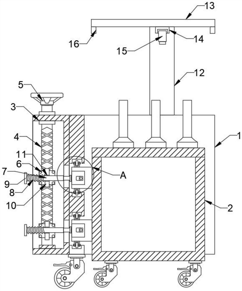
[0026] refer to Figure 1-4 , comprising a main body 1, one side of the main body 1 is fixedly connected with a detection cabinet 17, the top of the detection cabinet 17 is fixedly connected with a bearing tube 12, the inner side of the bearing tube 12 is provided with a movable rod 18, and the top of the movable rod 18 passes through the bearing groove 24 It runs through the top of the bearing tube 12, and the top of the movable rod 18 is fixedly connected to the top plate 13, the bottom of the top plate 13 is fixedly connected to the linear slide module 14, and the bottom of the linear slide module 14 is slidably connected to the visual camera 15, and The bottom of the top plate 13 is fixedly connected with a light source 16, one side of the main body 1 is provided with a working vehicle 2, and one side of the main body 1 is fixedly connected with a frame body 3, and the inner side of the frame body 3 is rotatably connected with a screw rod 4, and the upper part of the screw ...

Embodiment 2

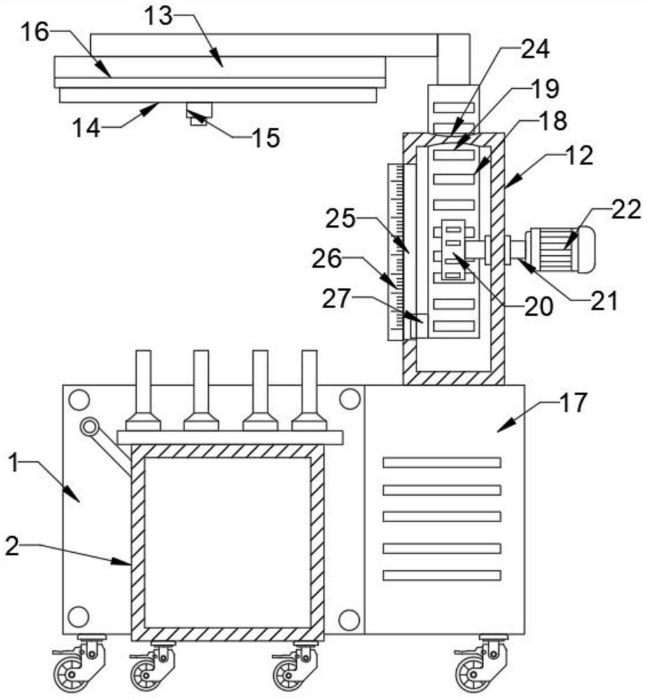
[0029] refer to Figure 1-4 One side of the outer wall of the carrying tube 12 is fixedly connected with a drive motor 22 by bolts, and the inner side of the carrying tube 12 is provided with a rotating rod 21, and one end of the rotating rod 21 is fixedly connected with a gear 20, wherein the other end of the rotating rod 21 is passed through a bearing The sleeve runs through the side wall of the bearing tube 12 and is connected to the output shaft of the drive motor 22. The movable rod 18 is fixedly connected with the rack 19, and the rack 19 is connected to the gear 20 through the engagement between the teeth. One side of the bearing tube 12 A vertical groove 25 is provided, and a slider 27 is fixedly connected to one side of the outer wall of the movable rod 18, and the slider 27 is slidingly connected to the inner wall of the bearing tube 12 through the vertical groove 25, and the outer wall of the bearing tube 12 is close to the side of the vertical groove 25. A scale 26...

Embodiment 3

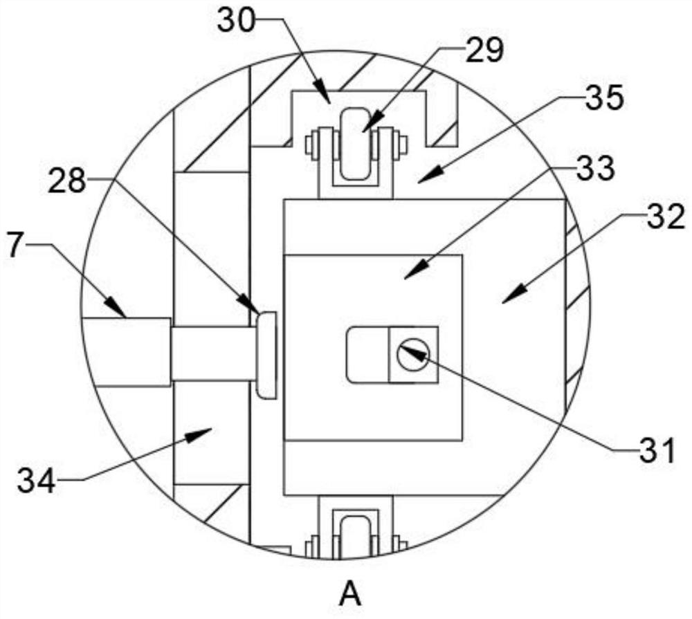
[0032] refer to Figure 1-4 The bottom end of the screw rod 4 is rotationally connected with the inner bottom of the frame body 3 through a rotating shaft, and the other end of the screw rod 4 runs through the top of the frame body 3 through a bearing sleeve, and the extension end of the screw rod 4 is fixedly connected with a handle 5, two The top and the bottom of each limit block 32 are all connected with a pulley 29 through the rotation of the rotating shaft, and the pulley 29 is connected by sliding between the inner wall of the chute 30 and the support groove 35, and the pulley 29 is used to slide in the chute 30, and then can further Ensure the stability of the work vehicle 2.


PUM


Abstract

The invention relates to the technical field of air valve detection, in particular to a wide-range air valve visual recognition device, and solves the problems that some air valves cannot be recognized due to the fact that visual cameras of an air valve recognition device in the prior art are fixed, and meanwhile, when an operation vehicle for operation is located below the recognition device, no limiting device exists, the instability of the working vehicle is caused, and the toppling of the air valve is caused. A wide-range air valve visual identification device comprises a main body, one side of the main body is fixedly connected with a detection cabinet, the top of the detection cabinet is fixedly connected with a bearing pipe, and the inner side of the bearing pipe is provided with a movable rod. According to the wide-range air valve visual recognition device, the linear sliding table module is introduced, so that the visual camera can move front and back in the length direction of the table top through the sliding table sliding block, the situation of missed recognition is avoided, the target air valve is located under the visual camera all the time, the fallen air valve can be effectively recognized, and the device is further triggered to give an alarm.

Description

technical field [0001] The invention relates to the technical field of gas valve detection, in particular to a large-scale visual recognition device for gas valves. Background technique [0002] Air valves are often used in daily production and equipment use. Air valves are components used to control gas in and out of cylinders in compressors. They are mainly composed of valve seats, valve plates, springs and lift limiters. Valves The lift height or closure between the sheet and the valve seat determines the size and airtightness of the gas passage. [0003] In the prior art, during the production of air valves, it is necessary to use an air valve identification device to observe whether the height and size of the air valve are qualified, and then the normal use of the air valve. The traditional air valve identification device is due to its visual camera They are all fixed, which will cause some air valves to be unrecognizable. At the same time, when the operating vehicle t...

Claims


Application Information

Patent Timeline
Patent Type & Authority Applications(China)
IPC IPC(8): G01N21/84G01N21/01
CPCG01N21/84G01N21/01
Inventor 朱之红鲁宏戴魏魏江剑丁佳范中良
Owner NANJING INT MARINE EQUIP & SPARES
Why Eureka
Try Eureka