Multi-electrode soil moisture detector
A soil moisture and detector technology, which is applied in the direction of material analysis, instruments, and measuring devices by electromagnetic means, can solve problems such as wear and tear and affect the work efficiency of users, and achieve the effect of increasing accuracy.
- Summary
- Abstract
- Description
- Claims
- Application Information
AI Technical Summary
Problems solved by technology
Method used
Image
Examples
Embodiment 1
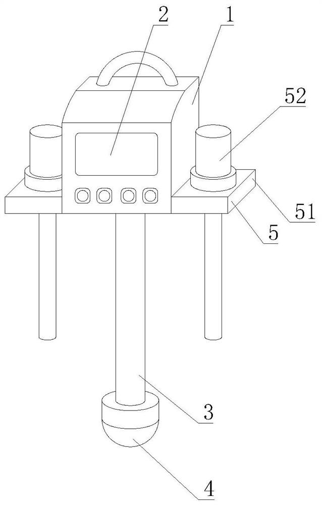
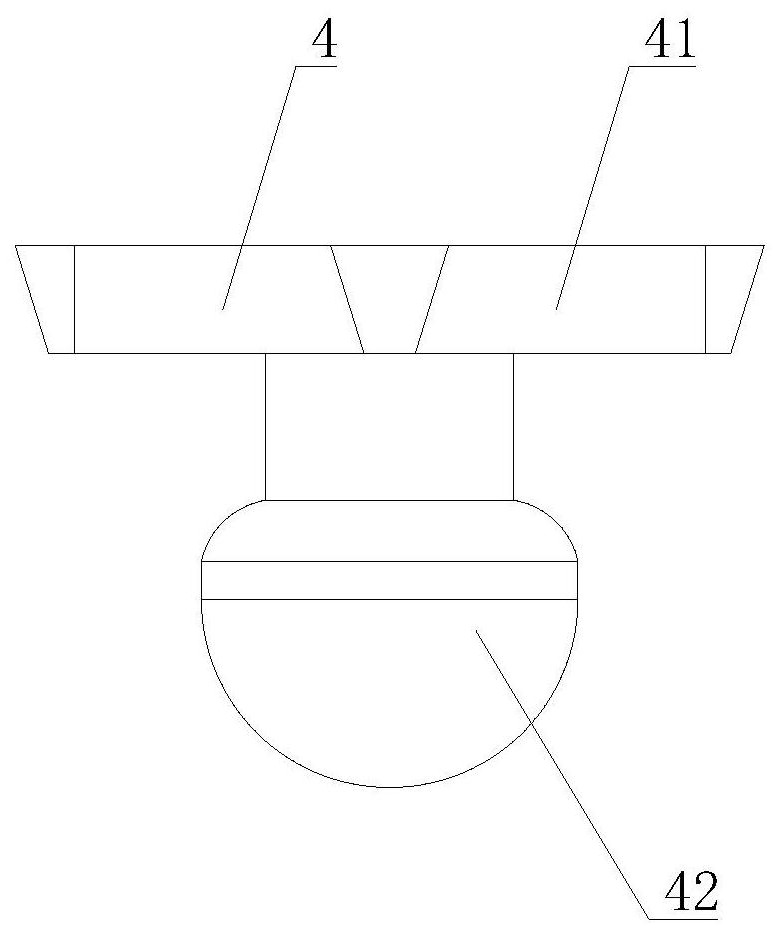
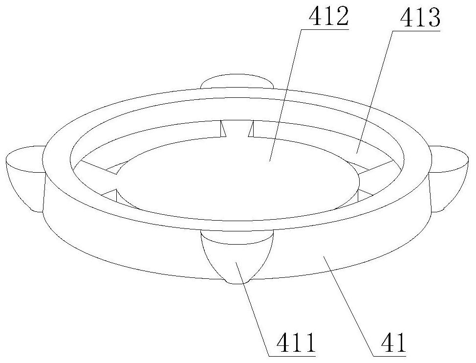
[0036] Such as Figure 1-10As shown, the present invention provides a multi-electrode soil moisture detector, comprising a multi-electrode soil moisture detector body 1, a display panel 2 is arranged on the front of the multi-electrode soil moisture detector body 1, and a multi-electrode soil moisture detector body 1 The bottom of the detection rod 3 is fixedly connected with the detection rod 3, and the detection rod 3 can be inserted into the soft soil to analyze the soil moisture, and the analysis result is displayed through the display panel 2. Both sides of the soil moisture detector body 1 are provided with a soil fastening mechanism 5, and the protection mechanism 4 includes a soil obstruction ring 41, and the bottom of the soil obstruction ring 41 is provided with a detection mechanism 42, and the outer wall of the soil obstruction ring 41 is fixedly installed There is a cup-shaped guide block 411, through the design of the cup-shaped guide block 411, the larger gravel...
Embodiment 2
[0038] Such as Figure 1-10 As shown, on the basis of Embodiment 1, the present invention provides a technical solution: preferably, the neutral plate 412 is movably connected to the bottom of the multi-electrode soil moisture detector body 1, and the detection mechanism 42 includes an alloy probe 421, an alloy probe The top of the 421 is fixedly equipped with a spacer plate 422, and the top of the spacer plate 422 is fixedly equipped with an arc-shaped block 423. By being provided with an alloy probe 421, the bottom of the detection rod 3 is prevented from directly contacting the soil, and the service life of the detection rod 3 is extended. By being provided with an arc-shaped block 423, the earth can be directed to the bottom of the earth-blocking ring 41, and the top of the arc-shaped block 423 is provided with an overvoltage detection mechanism 424, and the top of the overvoltage detection mechanism 424 is provided with a buffer mechanism 425, and the overvoltage detection...
Embodiment 3
[0040] Such as Figure 1-10 As shown, on the basis of Embodiment 1, the present invention provides a technical solution: preferably, the buffer mechanism 425 includes a top flow frame 4251, the bottom of the top flow frame 4251 is fixedly connected to the top of the pressure detection tube 4241, and the top flow frame The bottom of the inner cavity of 4251 is fixedly equipped with elastic parts 4252, the side of the inner cavity of the top flow frame 4251 is fixedly installed with an air bag 4253, and the top of the air bag 4253 is fixedly connected with a compression bag 4254, and the inner cavity of the compression bag 4254 is filled with silicone filler 4255 , the top of the compression bag 4254 is fixedly connected to the bottom of the soil barrier ring 41, and the air bag 4253 can buffer the impact force generated when the alloy probe 421 is in contact with the gravel, so as to avoid excessive impact force and affect the safety of the detection rod 3 The cushioning capaci...
PUM
 Abstract
Description
Claims
Application Information
 - R&D
- Intellectual Property
- Life Sciences
- Materials
- Tech Scout
- Unparalleled Data Quality
- Higher Quality Content
- 60% Fewer Hallucinations
Browse by: Latest US Patents, China's latest patents, Technical Efficacy Thesaurus, Application Domain, Technology Topic, Popular Technical Reports.
© 2025 PatSnap. All rights reserved.Legal|Privacy policy|Modern Slavery Act Transparency Statement|Sitemap|About US| Contact US: help@patsnap.com


