Improved buzzer and manufacturing process thereof

A manufacturing process and buzzer technology, which is applied in the direction of instruments, sounding devices, etc., can solve the problems of current reduction, impact of buzzer operation, and low production efficiency, so as to increase winding friction, ensure electrical connection performance, and improve The effect of production efficiency

Pending Publication Date: 2021-10-22
广东疆海五音电子科技有限公司
View PDF0 Cites 0 Cited by
  • Summary
  • Abstract
  • Description
  • Claims
  • Application Information

AI Technical Summary

Problems solved by technology

[0002] Traditional buzzer such as figure 1 As shown, the coil group 4 is electrically connected to the pin 1 through the PCB board 9. This structure will cause the production process of the buzzer to be cumbersome and have a certain impact on the operation of the buzzer; specifically, the general production process is as follows: ① Rivet the pin 1 on the PCB board 9; ② ​​After the winding of the coil group 4 is completed, solder the start and end of the coil group 4 to the corresponding pads on the PCB board 9, so that the coil group 4 and the pin 1 are electrically connected to each other ;③ Glue the PCB board and the support coil 9, and wait for the glue to solidify; ④After 3-4 hours, after the glue is solidified, assemble the components such as the magnetic ring 6, the vibrating plate 7 and the outer shell 8 in order, and then Dot glue on the edge again to seal and plug the hole, and then epoxy potting can be done after curing
In the traditional buzzer, since the pin 1 and the coil group 4 are electrically connected to each other through the PCB board 9, that is, the pin 1 and the coil group 4 need to be connected to the PCB board 9 through a welding process, which makes the production process cumbersome. The connection method often directly affects the electrical connection effect because of the welding quality; in addition, in the production process, the PCB board 9 needs to be glued around the periphery (that is, the above step ③, since the bonding object is the PCB board 9, the glue used is only Special glue can be selected, the curing time of the glue is long), during which it is necessary to wait for the glue to completely cure before proceeding to the next step, so the production of traditional buzzers cannot achieve uninterrupted assembly line production, and the production efficiency is low; In addition, PCB Board 9 electrically connects pin 1 to coil group 4 by printing related circuits, and the printed circuit will increase the resistance between pin 1 and coil group 4, and reduce the current reaching coil group 4, resulting in a decrease in power and power consumption. loss

Method used


Image

  • Improved buzzer and manufacturing process thereof
  • Improved buzzer and manufacturing process thereof
  • Improved buzzer and manufacturing process thereof

Examples


Embodiment Construction

[0026] The present invention will be further described below in conjunction with the accompanying drawings and embodiments.

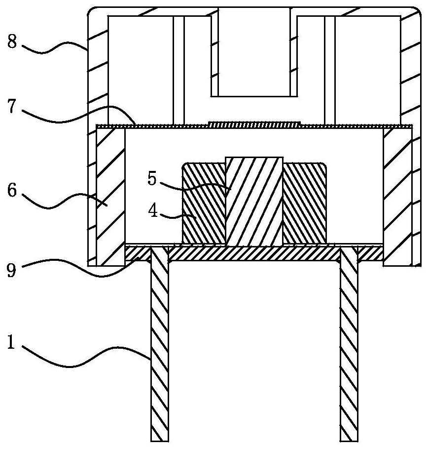
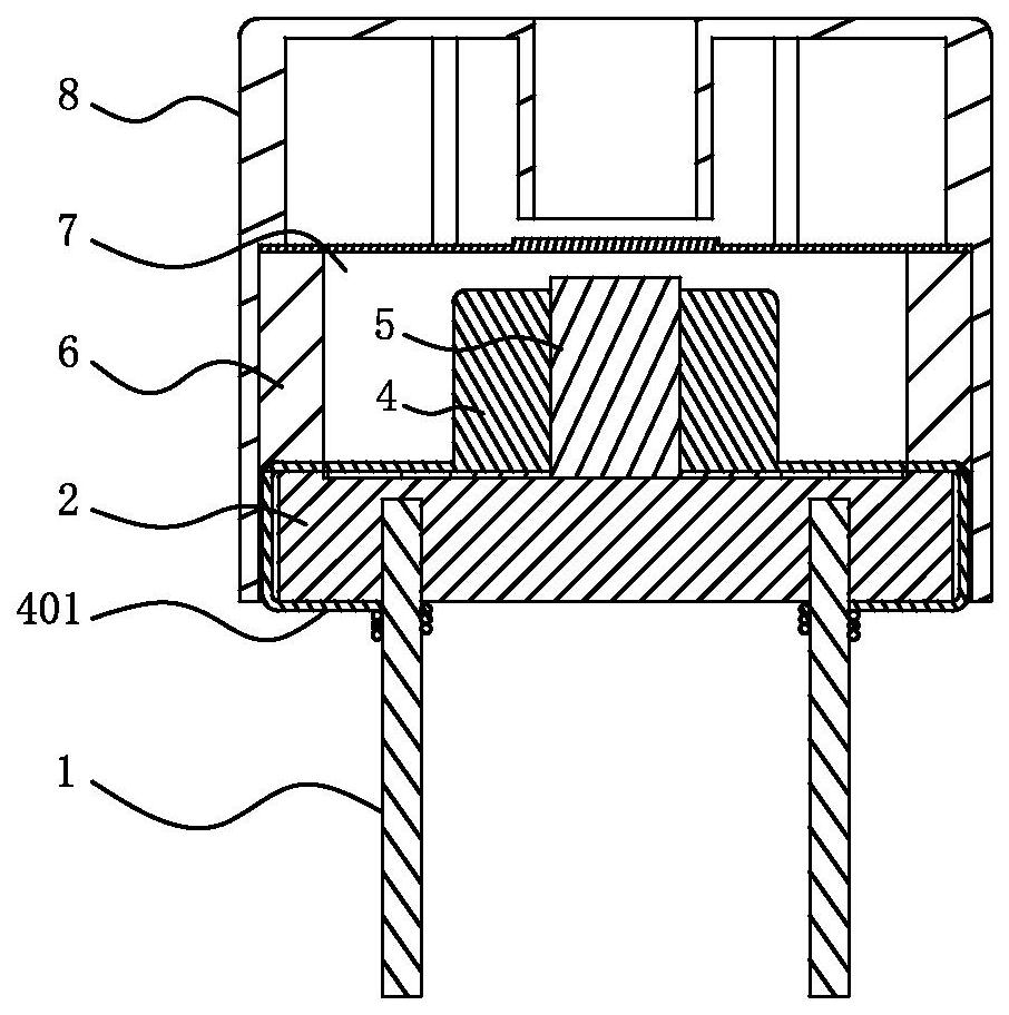
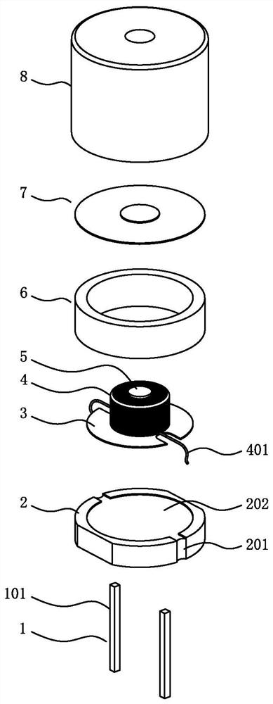
[0027] see Figure 1-Figure 3 , the buzzer involved in this embodiment includes a pin 1, a bottom cover 2, and a coil set 4; the pin 1 and the coil set 4 are respectively arranged on the bottom cover 2; the beginning and the end of the coil set 4 are respectively wound on the pin 1 , to directly electrically connect the corresponding pin 1. Compared with the traditional buzzer, the improved buzzer cancels the setting of the PCB board 9, and the pin 1 is directly electrically connected with the coil group 4. This structure can cancel the related welding process, and there is no need to fix the PCB board 9. Glue filling saves the process of waiting for the glue to solidify, so that the production of the buzzer can realize uninterrupted assembly line production, which greatly improves the production efficiency of the buzzer; in addition, pin 1 is directly...


PUM


Abstract

The invention relates to an improved buzzer and a manufacturing process thereof. The improved buzzer comprises a pins, a bottom cover and a coil assembly, the pins and the coil assembly are respectively arranged on the bottom cover; and the starting end and / or the tail end of the coil assembly are / is directly and electrically connected with the corresponding pins. The buzzer is simple and reasonable in structure, the production process can be simplified, and the production efficiency can be improved.

Description

technical field [0001] The invention relates to an electrical component, in particular to an improved buzzer and its manufacturing process. Background technique [0002] The traditional buzzer such as figure 1 As shown, the coil group 4 is electrically connected to the pin 1 through the PCB board 9. This structure will cause the production process of the buzzer to be cumbersome and have a certain impact on the operation of the buzzer; specifically, the general production process is as follows: ① Rivet the pin 1 on the PCB board 9; ② ​​After the winding of the coil group 4 is completed, solder the start and end of the coil group 4 to the corresponding pads on the PCB board 9, so that the coil group 4 and the pin 1 are electrically connected to each other ;③ Glue the PCB board and the support coil 9, and wait for the glue to solidify; ④After 3-4 hours, after the glue is solidified, assemble the components such as the magnetic ring 6, the vibrating plate 7 and the outer shell ...

Claims


Application Information

Patent Timeline
Patent Type & Authority Applications(China)
IPC IPC(8): G10K9/18
CPCG10K9/18
Inventor 丁爱勇
Owner 广东疆海五音电子科技有限公司
Why Eureka
Try Eureka