Satellite-borne flexible composite material shell surface deployable antenna device

A composite material and antenna device technology, which is applied to antennas, antennas, folded antennas and other directions suitable for movable objects, can solve the problem of reducing the number of back support ribs, and achieve reliable deployment process, high-precision shape retention capability, and storage. Small size effect

Pending Publication Date: 2021-10-22
BEIJING RES INST OF TELEMETRY +1
View PDF3 Cites 4 Cited by
  • Summary
  • Abstract
  • Description
  • Claims
  • Application Information

AI Technical Summary

Problems solved by technology

[0003] The present invention aims to solve the problem of improving the precision of the wire mesh deployable antenna, and provides a spaceborne flexible composite material shell surface deployable antenna device, which introduces the flexible composite material shell surface as the reflection surface of the antenna, and adopts th

Method used


Image

  • Satellite-borne flexible composite material shell surface deployable antenna device
  • Satellite-borne flexible composite material shell surface deployable antenna device
  • Satellite-borne flexible composite material shell surface deployable antenna device

Examples


Embodiment 1

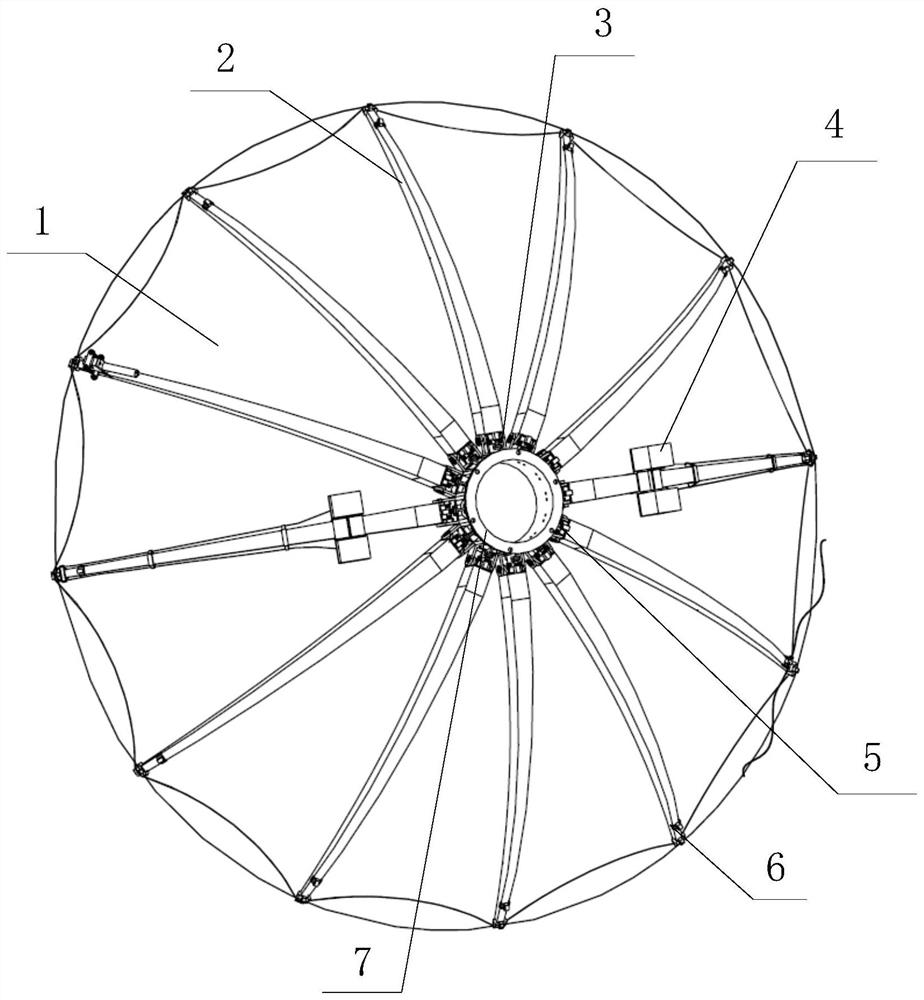
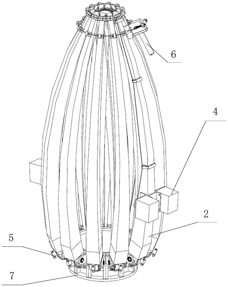
[0036] Such as figure 1 As shown, a space-borne flexible composite material shell surface deployable antenna device includes a flexible composite material shell surface 1, and N radial support ribs 2 with variable cross-sections arranged radially on the back of the flexible composite material shell surface 1 at equal angles. The constant moment hinge 3 at the starting end of the variable-section radial support rib 2, the deployment synchronization device 4 arranged in the middle of the variable-section radial support rib 2, and the expansion limit adjustment provided at the starting end of each variable-section radial support rib 2 Device 5, the locking and unlocking device 6 arranged at the end position of the radial support rib 2 with variable cross section and the annular center body 7 connected to the starting end of each radial support rib 2 with variable cross section; the synchronization device 4 and The locking and unlocking devices 6 are located on the back of the fle...

Embodiment 2

[0040] Such as figure 1 As shown, a space-borne flexible composite material shell surface deployable antenna device includes a flexible composite material shell surface 1, and N radial support ribs 2 with variable cross-sections arranged radially on the back of the flexible composite material shell surface 1 at equal angles. The constant moment hinge 3 at the starting end of the variable-section radial support rib 2, the deployment synchronization device 4 arranged in the middle of the variable-section radial support rib 2, and the expansion limit adjustment provided at the starting end of each variable-section radial support rib 2 Device 5, the locking and unlocking device 6 arranged at the end position of the radial support rib 2 with variable cross section and the annular center body 7 connected to the starting end of each radial support rib 2 with variable cross section; the synchronization device 4 and The locking and unlocking devices 6 are located on the back of the fle...

Embodiment 3

[0055] Such as figure 1 As shown, a space-borne flexible composite material shell can expand the working state form of the antenna device, which is the basic form of the present invention. It consists of a flexible composite material shell 1, a variable cross-section radial support rib 2, a constant moment hinge 3, Synchronization device 4, expansion limit adjustment device 5, locking and unlocking device 6, central body 7 constitute. The number of radial support ribs 2 with variable cross-sections is determined according to the shape and surface accuracy requirements and the storage volume after deployment. After the deployment is completed, the flexible composite material shell surface 1 is in an initial stress-free state, and is fixed to the radial support ribs 2 with variable cross-section by adhesive bonding. The radial support ribs 2 with variable cross-sections provide the mechanical interfaces of the unfolding constant moment hinge 3 , the synchronizing device 4 , the...


PUM


Abstract

The invention provides a spaceborne flexible composite material shell surface deployable antenna device. The device comprises a flexible composite material shell surface, a variable cross-section radial supporting rib, a constant torque hinge, an unfolding synchronizing device, an unfolding limiting adjusting device, a locking and unlocking device and a center body. The variable cross-section supporting ribs are driven by the constant-torque hinges to rotate and drive the flexible composite shell face to be unfolded. The unfolding synchronization device is used for limiting the unfolding speed of the variable cross-section supporting ribs. The unfolding limiting adjusting device is used for adjusting the in-place precision after the variable cross-section radial supporting rib is unfolded in place. A flexible composite material shell surface is introduced as a reflecting surface of the antenna. Under the same profile precision requirement, compared with a metal wire mesh reflector antenna with the same size, a tension cable system is not needed, and the number of back supporting ribs is reduced. According to the invention, a new technical approach is provided for the spaceborne antenna load, wherein the device has the advantages of being small in storage size, reliable in unfolding process, high in unfolding surface precision and the like, and is suitable for communication of different frequency bands of the spaceborne antenna and the like.

Description

technical field [0001] The invention relates to the technical field of antennas, in particular to a spaceborne flexible composite material shell surface expandable antenna device. Background technique [0002] The deployable antenna is an effective measure to solve the typical contradiction between the demand for spaceborne large-aperture antennas and the load limit of vehicles. For space deployable reflector antennas, according to the different forms of folding structure, it can be roughly divided into solid surface deployable antennas, mesh deployable antennas, inflatable deployable antennas, and two or more ways to combine deployable antennas and other types. Among them, the mesh-shaped deployable antenna using wire mesh has the advantages of strong size scalability, high storage efficiency, and light weight. This type of reflector antenna has been widely used, and its diameter ranges from a few meters to nearly a hundred meters. Since the wire mesh surface does not have...

Claims


Application Information

Patent Timeline
IPC IPC(8): H01Q15/16H01Q1/08H01Q19/12H01Q1/28
CPCH01Q15/161H01Q19/12H01Q1/288
Inventor 杨留义刘昊杨雨田姜智先史永康
Owner BEIJING RES INST OF TELEMETRY
Why Eureka
Try Eureka