
Ultrahigh current monitoring and processing system

A current monitoring and ultra-high technology, which is applied in the direction of measuring devices, electrical components, electrical equipment structural parts, etc., can solve the problems of increasing measurement errors, low current detection accuracy, and difficulty in measuring currents containing DC components. Achieve the effects of weakening power, avoiding interference, and avoiding errors caused by inaccurate measurements

Active Publication Date: 2021-10-22
深圳普泰电气有限公司
View PDF9 Cites 0 Cited by
  • Summary
  • Abstract
  • Description
  • Claims
  • Application Information

AI Technical Summary

Problems solved by technology

[0002] In the process of ultra-high current flow, if the temperature characteristics of the components are not good, the current detection accuracy will not be high, and the sensor is very susceptible to drift, and it is difficult to measure the current containing DC components slightly affected by point drift. The measurement coil The current flowing in the medium needs to exclude external interference factors, the influence of noise and other factors in the induction process, and it is easy to exert sound wave pressure on the outside of the coil. When the noise is too large, the side wall of the coil will vibrate and increase. measurement error

Method used


Image

  • Ultrahigh current monitoring and processing system
  • Ultrahigh current monitoring and processing system
  • Ultrahigh current monitoring and processing system

Examples


Embodiment 1

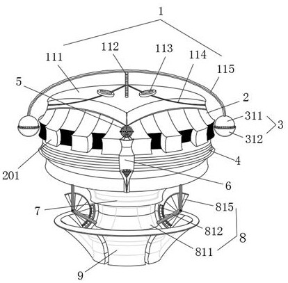
[0045] see figure 1, an ultra-high current monitoring and processing device, comprising a spring mechanism 1, the interior of the spring mechanism 1 includes a movable plate 111, an elastic band 114 is connected through the top side wall of the movable plate 111, and the side wall of the elastic band 114 runs through A movable ring 113 is connected, a compression spring 112 is connected through the middle part of the top side wall of the movable plate 111, an elastic spring 115 is connected through the top of the compression spring 112, and a rolling mechanism 3 is connected through the bottom end of the elastic spring 115. The interior includes a movable ball 311, the side wall of the movable ball 311 is connected with a hemispherical shell 312, the bottom side wall of the elastic mechanism 1 is connected with a movable block 2, and the side wall of the movable block 2 is connected with a pressing block. 201, the bottom end of the movable block 2 is connected with a laminated...

Embodiment 2

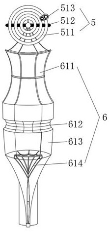
[0050] see Figure 1-2 , an ultra-high current monitoring and processing device, comprising a spring mechanism 1, the interior of the spring mechanism 1 includes a movable plate 111, an elastic band 114 is connected through the top side wall of the movable plate 111, and the side wall of the elastic band 114 runs through A movable ring 113 is connected, a compression spring 112 is connected through the middle part of the top side wall of the movable plate 111, an elastic spring 115 is connected through the top of the compression spring 112, and a rolling mechanism 3 is connected through the bottom end of the elastic spring 115. The side wall of the bottom end of 1 is connected with a movable block 2, the side wall of the movable block 2 is connected with a pressing block 201, the bottom of the movable block 2 is connected with a laminated body 4, and the side wall of the laminated body 4 is The down-pressing mechanism 6 is connected through, and the inside of the down-pressing...

Embodiment 3

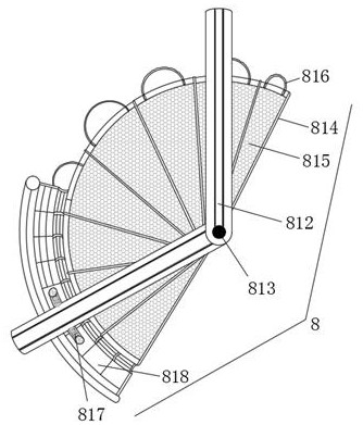
[0053] see figure 1 and image 3 , an ultra-high current monitoring and processing device, comprising a spring mechanism 1, the interior of the spring mechanism 1 includes a movable plate 111, an elastic band 114 is connected through the top side wall of the movable plate 111, and the side wall of the elastic band 114 runs through A movable ring 113 is connected, a compression spring 112 is connected through the middle part of the top side wall of the movable plate 111, an elastic spring 115 is connected through the top of the compression spring 112, and a rolling mechanism 3 is connected through the bottom end of the elastic spring 115. The side wall of the bottom end of 1 is connected with a movable block 2, the side wall of the movable block 2 is connected with a pressing block 201, the bottom of the movable block 2 is connected with a laminated body 4, and the side wall of the laminated body 4 is A pressing mechanism 6 is connected through it, and a rotating mechanism 5 i...


PUM


Abstract

The invention relates to the technical field of current monitoring, and discloses an ultra-high current monitoring and processing device. The device comprises a springing mechanism, a movable plate is arranged in the springing mechanism, an elastic belt is connected to the top side wall of the movable plate in a penetrating mode, and a movable ring is connected to the side wall of the elastic belt in a penetrating mode; a compression spring is connected to the middle of the top side wall of the movable plate in a penetrating mode, an elastic spring is connected to the top end of the compression spring in a penetrating mode, and a rolling mechanism is connected to the bottom end of the elastic spring in a penetrating mode. The bottom end of the elastic spring drives the side wall of the movable ball to rotate, and the bottom side wall of the movable ball drives the side wall of the hemispherical shell to rotate and roll. The side wall of the hemispherical shell is driven to rotate on the outer side wall of the movable block, and the side wall of the movable block is pushed to be attached to and close to the side wall of the pressing block; finally, the side walls of the movable block and the pressing block are scraped and pressed, so that sound waves are dispersed between the side walls of the movable block and the pressing block, the force of the sound waves can be weakened, and interference caused by too strong sound waves is avoided.

Description

technical field [0001] The invention relates to the technical field of current monitoring, in particular to an ultra-high current monitoring and processing system. Background technique [0002] In the process of ultra-high current flow, if the temperature characteristics of the components are not good, the current detection accuracy will not be high, and the sensor is extremely susceptible to drift. It is difficult to measure the current containing DC components slightly affected by point drift. The measurement coil The current flowing through the coil needs to eliminate the influence of external interference factors, noise and other factors in the induction process, and it is easy to exert sound wave pressure on the outside of the coil. When the noise is too large, the side wall of the coil will vibrate and increase. measurement error. Contents of the invention [0003] In order to solve the above problems, the present invention provides the following technical solutions...

Claims


Application Information

Patent Timeline
Patent Type & Authority Applications(China)
IPC IPC(8): H05K5/02H05K7/14H05K7/20G01D21/02
CPCH05K5/0217H05K5/0247G01D21/02H05K7/14H05K7/20136H05K7/20181
Inventor 李凯钟正水
Owner 深圳普泰电气有限公司
Learn More