Precise automatic lifting device for manipulator

An automatic lifting and manipulator technology, applied in the direction of manipulators, manufacturing tools, etc., can solve problems such as safety accidents, shaking of the counterweight box, limited space of the counterweight box, etc., and achieve the goal of improving safety performance, safety, stability and safety Effect

Pending Publication Date: 2021-10-26
宜世摩上海机电科技有限公司
View PDF0 Cites 0 Cited by
  • Summary
  • Abstract
  • Description
  • Claims
  • Application Information

AI Technical Summary

Problems solved by technology

[0003] However, the existing special-purpose manipulators in the field of semiconductor packaging and testing have the following problems in the process of use: (1) the prior art implementation is balanced, similar to the fixed pulley, that is, both sides of the synchronous wheel, one side is the load (test Machine), one side is a balance weight (counterweight box), the mass and gravity of both sides are equal in theory, when the ground on which the manipulator is placed is tilted or when the manipulator is transported, the counterweight box itself is not restrained, and it is easy to cause the counterweight box to be in the cone. The body-shaped space continuously shakes and bumps into the inner cavity of the manipulator column. In severe cases, it is easy to cause an imbalance of the center of gravity, thereby causing a safety accident; (2) For different testing machines, the number of counterweight plates needs to be continuously adjusted on the counterweight side to achieve balance
For different loads, it is inefficient to disassemble the counterweights. In addition, due to the limited space of the counterweight box, the maximum load to be balanced is limited by the number of counterweights and the load lifting cannot be accurately controlled.

Method used


Image

  • Precise automatic lifting device for manipulator
  • Precise automatic lifting device for manipulator

Examples


Embodiment Construction

[0014] The following will clearly and completely describe the technical solutions in the embodiments of the present invention with reference to the accompanying drawings in the embodiments of the present invention. Obviously, the described embodiments are only some, not all, embodiments of the present invention. Based on the embodiments of the present invention, all other embodiments obtained by persons of ordinary skill in the art without making creative efforts belong to the protection scope of the present invention.

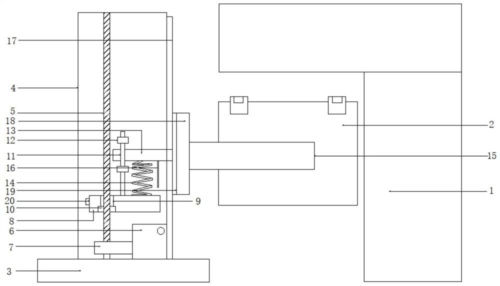
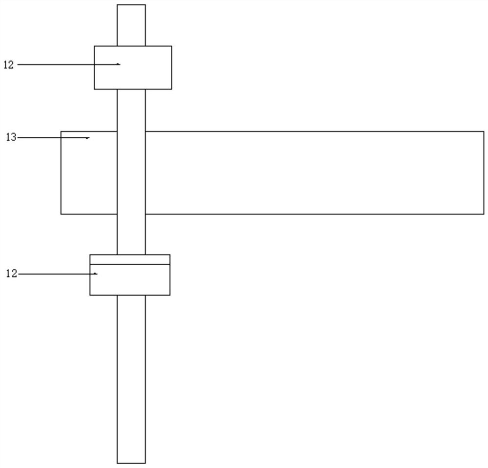
[0015] see Figure 1-2 , the present invention provides a technical solution: a precision automatic lifting device for a manipulator, comprising a horizontally arranged base 3 and a column 4 vertically installed on the base 3, the inside of the column 4 is vertically provided with a threaded spindle 5, and the threaded spindle 5 The lower end is rotatably inserted on the base 3 and the upper end is rotatably connected with the inner wall of the column 4. A dri...


PUM


Abstract

The invention discloses a precise automatic lifting device for a manipulator. The precise automatic lifting device for the manipulator comprises a horizontally-arranged base and a stand column vertically installed on the base, wherein a threaded main shaft is vertically arranged in the stand column, the lower end of the threaded main shaft is rotationally inserted into the base in a penetrating mode, the upper end of the threaded main shaft is rotationally connected with the inner wall of the stand column, and a driving motor is arranged at the lower right corner of the threaded main shaft; and a synchronous belt is installed at a power output end of the driving motor and embedded in the lower end of the threaded main shaft in a sleeved mode, a sliding block is horizontally arranged above the synchronous belt, an installation opening is formed in the sliding block, a main shaft nut is embedded in the installation opening, and meanwhile a high-strength combined spring and a safety switch are included. The invention designs a manipulator device capable of precisely and automatically lifting, so that the capacity of bearing the upper limit of a load by the manipulator is improved, the safety performance of the manipulator special for the field of semiconductor assembly and test is improved, real-time monitoring is carried out, and the load capacity is improved.

Description

technical field [0001] The invention relates to the technical field of an automatic load lifting structure of a semiconductor packaging and testing manipulator, in particular to a precise automatic lifting device for a manipulator. Background technique [0002] The testing machine is an important product in the semiconductor packaging and testing process. In normal testing work, the testing machine needs to be held in a stable position. When different brands and types of testing machines are matched with different brands and types of probe machines and sorting machines, it is necessary to Adjust the height, angle and other parameters of the testing machine, while the spatial position of the testing machine needs to be controlled by an industry-specific manipulator. The special manipulator for semiconductor packaging and testing needs to adapt to testing machines of different weights. The industry generally adopts the principle of balance for design and manufacture. The mani...

Claims


Application Information

Patent Timeline
Patent Type & Authority Applications(China)
IPC IPC(8): B25J19/00B25J19/06
CPCB25J19/00B25J19/06
Inventor 约瑟夫·温伯格维尔纳·胡伯
Owner 宜世摩上海机电科技有限公司
Why Eureka
Try Eureka