Supercharge Your Innovation With Domain-Expert AI Agents!

Triangular bracket structure for bridge and construction method thereof

A technology for triangular brackets and bridges. It is applied in bridges, bridge construction, erection/assembly of bridges, etc. It can solve problems such as the inability to ensure the levelness of beams and affect the construction quality, and achieve good support and convenient installation.

Pending Publication Date: 2021-10-26
NANTONG ROAD & BRIDGE ENG CO LTD
View PDF7 Cites 0 Cited by
  • Summary
  • Abstract
  • Description
  • Claims
  • Application Information

AI Technical Summary

Problems solved by technology

The levelness of the beam cannot be guaranteed, which affects the construction quality

Method used


Image

  • Triangular bracket structure for bridge and construction method thereof
  • Triangular bracket structure for bridge and construction method thereof
  • Triangular bracket structure for bridge and construction method thereof

Examples


Embodiment 1

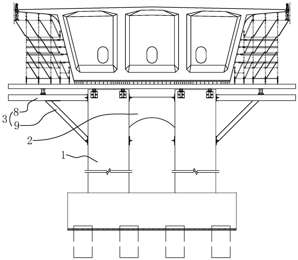
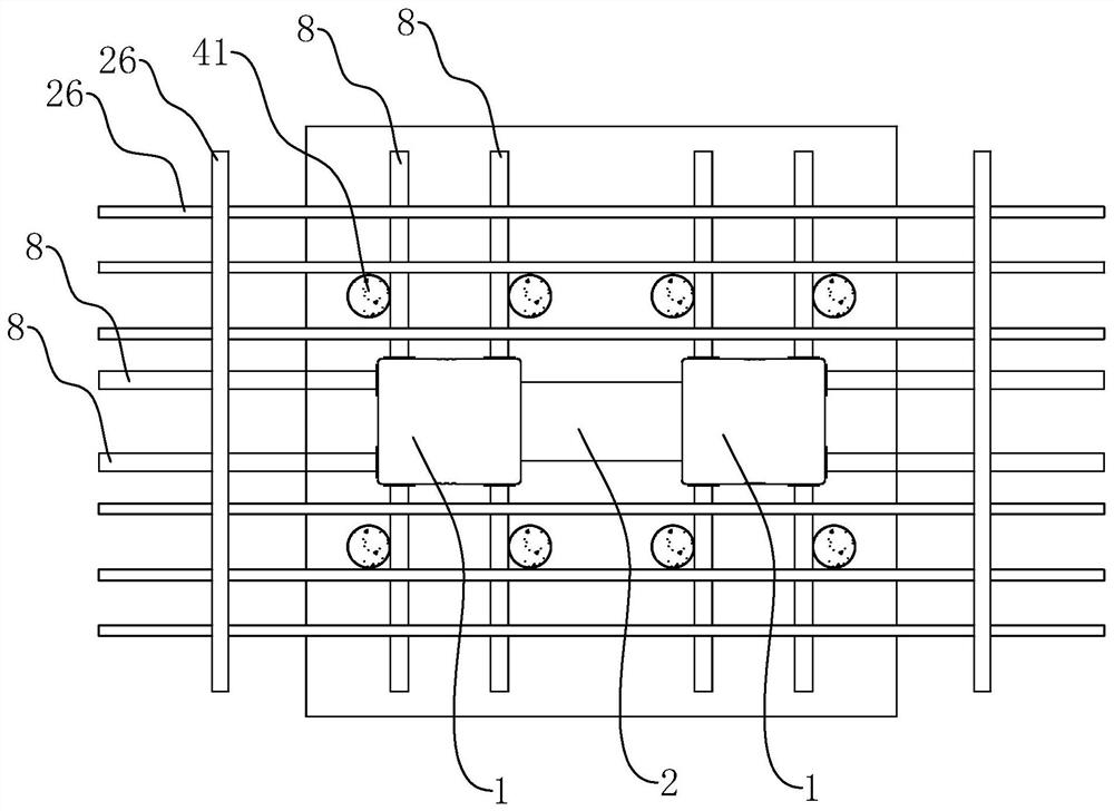
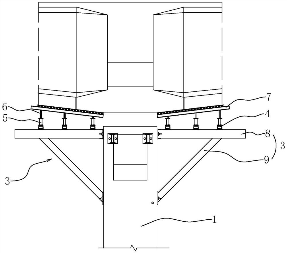
[0052] Embodiment 1 of the present application discloses a triangular bracket structure for a bridge. refer to figure 1 with figure 2 , a triangular bracket structure includes a bridge pier 1 and a temporary anchor pier 41 . refer to figure 2 with image 3 , There are two bridge piers 1 and the two bridge piers 1 are fixedly connected by a connecting bridge 2 . A load-bearing system is installed on the pier 1. The load-bearing system includes a triangular bracket 3, a sand cylinder 4, a horizontal bridge distribution beam 5, a vertical adjustment short column 6 and a longitudinal bridge distribution beam 7 from bottom to top.

[0053] refer to figure 1 with image 3 , the triangular bracket 3 includes a crossbeam 8 and a diagonal bar 9, the crossbeam 8 is arranged horizontally, the diagonal bar 9 is arranged obliquely and fixedly connected to the crossbeam 8 after construction, so that the triangular bracket 3 forms a triangle as a whole.

[0054] refer to figure 1 ...

Embodiment 2

[0065] Embodiment 2 is based on the construction technology of triangular bracket 3 in embodiment 1, comprises the following steps,

[0066] S1, welding and installing the support rod 26 arranged in the horizontal direction on the temporary anchorage pier 41;

[0067] S2. An anchor assembly 42 is installed on the embedded pipe 12 of the bridge pier 1, so that both ends of the embedded pipe 12 are fixedly installed with anchoring steel plates 13;

[0068] S3, welding and fixing the first connection seat 16 on the triangular bracket 3 to be installed on the corresponding anchor steel plate 13;

[0069] S4, sliding the sliding seat 40 relative to the beam 8, so that the second connecting seat 18 and the pier 1 are spaced apart;

[0070] S5, slide the guide seat 20 relative to the inclined bar 9 until the second connecting seat 18 is aligned with the anchor steel plate 13 to be installed;

[0071] S6, then slide the sliding seat 40 relative to the beam 8, make the second connect...

Embodiment 3

[0076] refer to Figure 11 with Figure 12 , The difference between Embodiment 3 and Embodiment 1 is that the adjustment component 19 and the compensation component 17 are different. The adjusting assembly 19 includes a first rotating base 29 rotatably connected to the second connecting base 18 and a driving member 30 for driving the first rotating base 29 to rotate relative to the second connecting base 18 . The lower end of the oblique rod 9 is welded and fixed to the first rotating seat 29 , and an angle groove 31 is formed between the first rotating seat 29 and the second connecting seat 18 . The opening end of the included angle groove 31 is provided with a mounting plate 32 , and the mounting plate 32 is fixedly connected to the side wall of the second connecting seat 18 facing away from the pier 1 . refer to Figure 12 with Figure 13 , the driving member 30 includes an adjusting block 33 , an adjusting bolt 34 rotatably connected to the mounting plate 32 , and a gu...


PUM


Abstract

The invention discloses a triangular bracket structure for a bridge pier. The triangular bracket structure comprises the bridge pier and triangular brackets, wherein each triangular bracket comprises a cross beam and an inclined rod, embedded pipes are arranged in the bridge pier, one triangular bracket corresponds to two embedded pipes, one end of the cross beam is fixedly connected with a first connecting base, and an upper end of the inclined rod is installed on the cross beam through a compensation assembly; a second connecting base is installed at a lower end of the inclined rod through an adjusting assembly and fixedly installed on the other embedded pipe, the adjusting assembly is used for driving a lower end of the inclined rod to move relative to the second connecting base in the inclined direction, and the compensation assembly is used for compensating the horizontal amount of movement of a lower end of the inclined rod in the inclined direction; the cross beam can be installed on the embedded pipe through the first connecting base firstly, then the position of a lower end of the inclined rod is adjusted through the adjusting assembly, the second connecting base corresponds to the other embedded pipe, and then the second connecting base is installed on the embedded pipe. Under the condition that levelness of the cross beam is guaranteed as much as possible, the triangular bracket can be installed, and the construction quality is improved.

Description

technical field [0001] The present application relates to the field of road and bridge construction, in particular to a triangular bracket structure for bridges and a construction method thereof. Background technique [0002] At present, in the construction of the upper structure of the continuous steel bridge by the hanging basket method, the triangle bracket method is commonly used in the construction of the O block of the main bridge box girder. [0003] For example, the patent application number 201420555766.1 discloses a cantilevered box girder triangular bracket fastener connection structure, including bridge piers, triangular brackets are arranged symmetrically on both sides of the bridge pier, embedded pipes are arranged in the bridge piers, and the triangular brackets pass through The embedded pipe is fixedly installed on the side wall of the pier, and one triangular bracket corresponds to two embedded pipes. The triangular bracket consists of beams and diagonal br...

Claims


Application Information

Patent Timeline
Patent Type & Authority Applications(China)
IPC IPC(8): E01D21/00E01D21/10
CPCE01D21/00E01D21/10
Inventor 单光明季海萍高小军曹小华陆海波徐相程陈晓玲唐玉婷
Owner NANTONG ROAD & BRIDGE ENG CO LTD
Features
  • R&D
  • Intellectual Property
  • Life Sciences
  • Materials
  • Tech Scout
  • Unparalleled Data Quality
  • Higher Quality Content
  • 60% Fewer Hallucinations
Learn More