a protective roof
A ceiling and protective panel technology, applied in the direction of roof, general water supply saving, machine/engine, etc., can solve the problems of unfavorable processing and production, not easy to breathe, and affect the reception of sunlight, etc., to improve efficiency and ensure the effect of breathability
- Summary
- Abstract
- Description
- Claims
- Application Information
AI Technical Summary
Problems solved by technology
Method used
Image

Examples
Embodiment 1
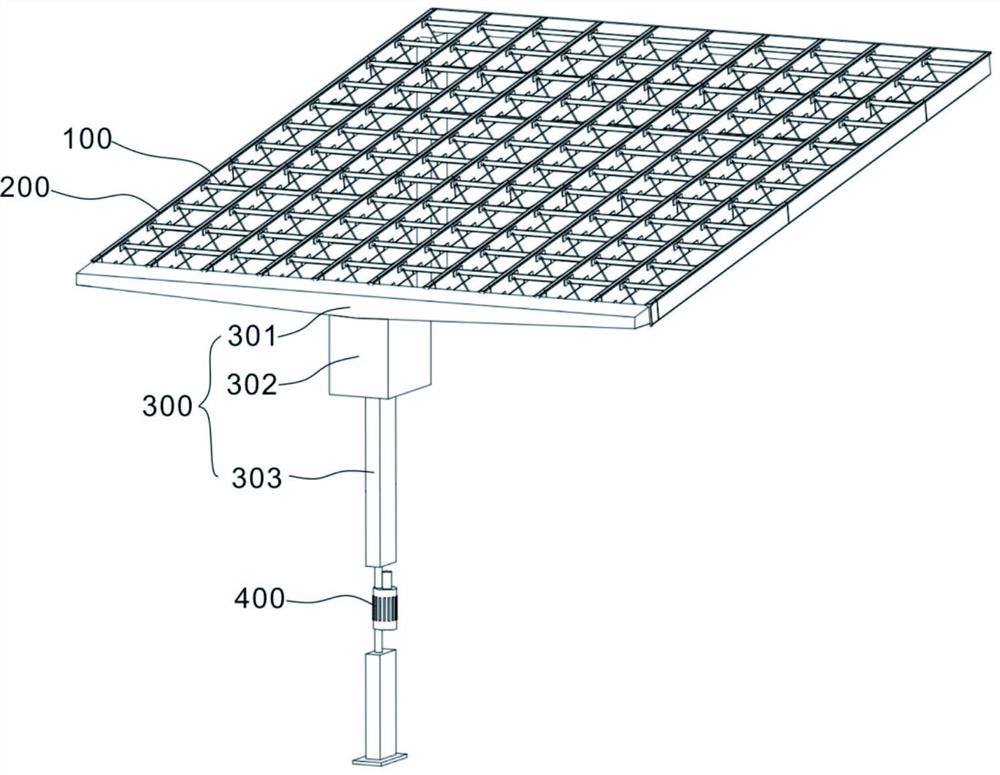
[0028] refer to figure 1 with Figure 3~Figure 7 , is the first embodiment of the present invention, which provides a protective ceiling, including a support component 100 , a protection component 200 , and a collection component 300 .
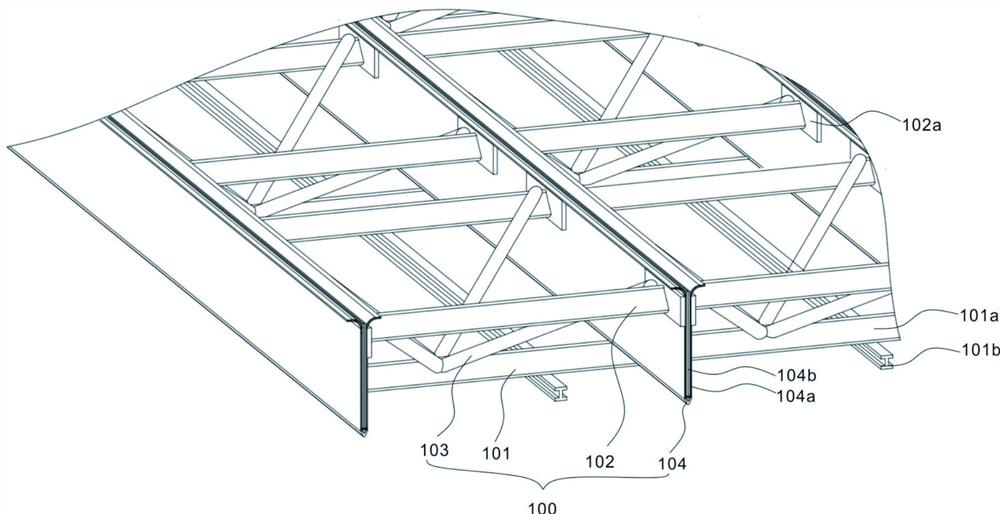
[0029] The supporting component 100 includes a fixing frame 101 , a supporting rod 102 , a pull rod 103 and a base 104 . The base 104 is provided with two groups of side plates 104a, the base 104 and the side plates 104a are integrally formed or fixedly connected together, and a receiving groove 104b is formed between the side plates 104a, and the two groups of side plates 104a are symmetrically distributed on both sides of the receiving groove 104b. The plate 104a and the receiving groove 104b are vertically provided with several through grooves 104c, the through grooves 104c vertically penetrate the bottom of the side plate 104a and the receiving groove 104b, one end of the pull rod 103 is arranged on the fixed frame 101, and the pull rod 1...
Embodiment 2
[0033] refer to figure 1 , figure 2 with Figure 4~Figure 8 , is the second embodiment of the present invention. This embodiment is based on the previous embodiment. The side of the fixing frame 101 close to the collecting part 300 is inclined downward, which is beneficial to guide rainwater to flow down quickly and prevent rainwater from accumulating. The fixed frame 101 includes several cross bars 101a and several longitudinal bars 101b, the cross bars 101a are arranged parallel to the support bars 102, the longitudinal bars 101b are arranged perpendicular to the cross bars 101a, a grid shape is formed between the cross bars 101a and the longitudinal bars 101b, and they are fixedly connected Together, it is beneficial to improve the overall structural strength of the fixing frame 101 while reducing its own weight. Two ends of the support rod 102 are connected to one side of the fixed plate 102a, and the other side of the fixed plate 102a is connected to the side plate 104...
Embodiment 3
[0043] refer to figure 2 , image 3 with Figure 9~Figure 11 , is the third embodiment of the present invention, which is based on the above two embodiments,
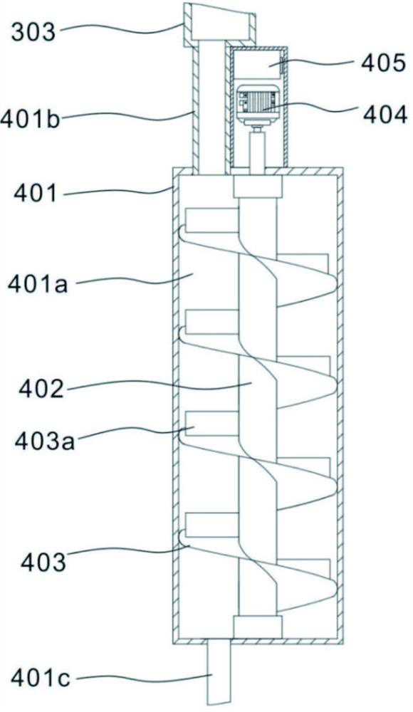
[0044] Please refer to figure 2 with image 3, and also includes a power generation component 400 , the power generation component 400 includes an outer shell 401 , a mandrel 402 , a spiral plate 403 , a generator 404 and a storage battery 405 . The outer casing 401 is provided with a housing cavity 401a, the top of the outer casing 401 is connected to the water inlet pipe 401b, and the water inlet pipe 401b is connected to the end of the diversion pipe 303 away from the water storage tank 302, so that the water in the diversion pipe 303 enters the water storage tank 302 through the water inlet pipe 401b Inside: the bottom of the outer casing 401 is connected to the water outlet pipe 401c, which is convenient to discharge the water in the water storage tank 302 through the water outlet pipe 401c; the water inlet p...
PUM
 Abstract
Description
Claims
Application Information
 - R&D Engineer
- R&D Manager
- IP Professional
- Industry Leading Data Capabilities
- Powerful AI technology
- Patent DNA Extraction
Browse by: Latest US Patents, China's latest patents, Technical Efficacy Thesaurus, Application Domain, Technology Topic.
© 2024 PatSnap. All rights reserved.Legal|Privacy policy|Modern Slavery Act Transparency Statement|Sitemap