
Low-cost and high-efficiency tool structure for battery shell glue filling

A low-cost technology for battery casings, which is applied to devices and coatings for coating liquid on the surface, which can solve the problems of wasting colloid, increasing the cost of manual wiping, and lacking the consistency and reliability of glue filling and continuous maintenance. Achieve the effects of improving efficiency, reducing processing time, and improving consistency

Active Publication Date: 2021-10-29
飞毛腿能源科技有限公司
View PDF8 Cites 0 Cited by
  • Summary
  • Abstract
  • Description
  • Claims
  • Application Information

AI Technical Summary

Problems solved by technology

[0004] Usually, glue is dispensed on the surface of the glue tank on the bottom case. After the cover is closed, the screws are locked, and the glue overflows to the outside at the unsealed place between the bottom case and the top cover. The glue on the outside needs to be wiped, which wastes the glue. It also increases the cost of manual wiping; and in the past, it was manually operated or semi-automatically operated, lacking the consistency of the glue filling and the continuous maintenance of reliability, requiring each battery pack to be tested for airtightness

Method used


Image

  • Low-cost and high-efficiency tool structure for battery shell glue filling
  • Low-cost and high-efficiency tool structure for battery shell glue filling
  • Low-cost and high-efficiency tool structure for battery shell glue filling

Examples


Embodiment Construction

[0030] In order to better explain the present invention and facilitate understanding, the present invention will be described in detail below through specific embodiments in conjunction with the accompanying drawings.

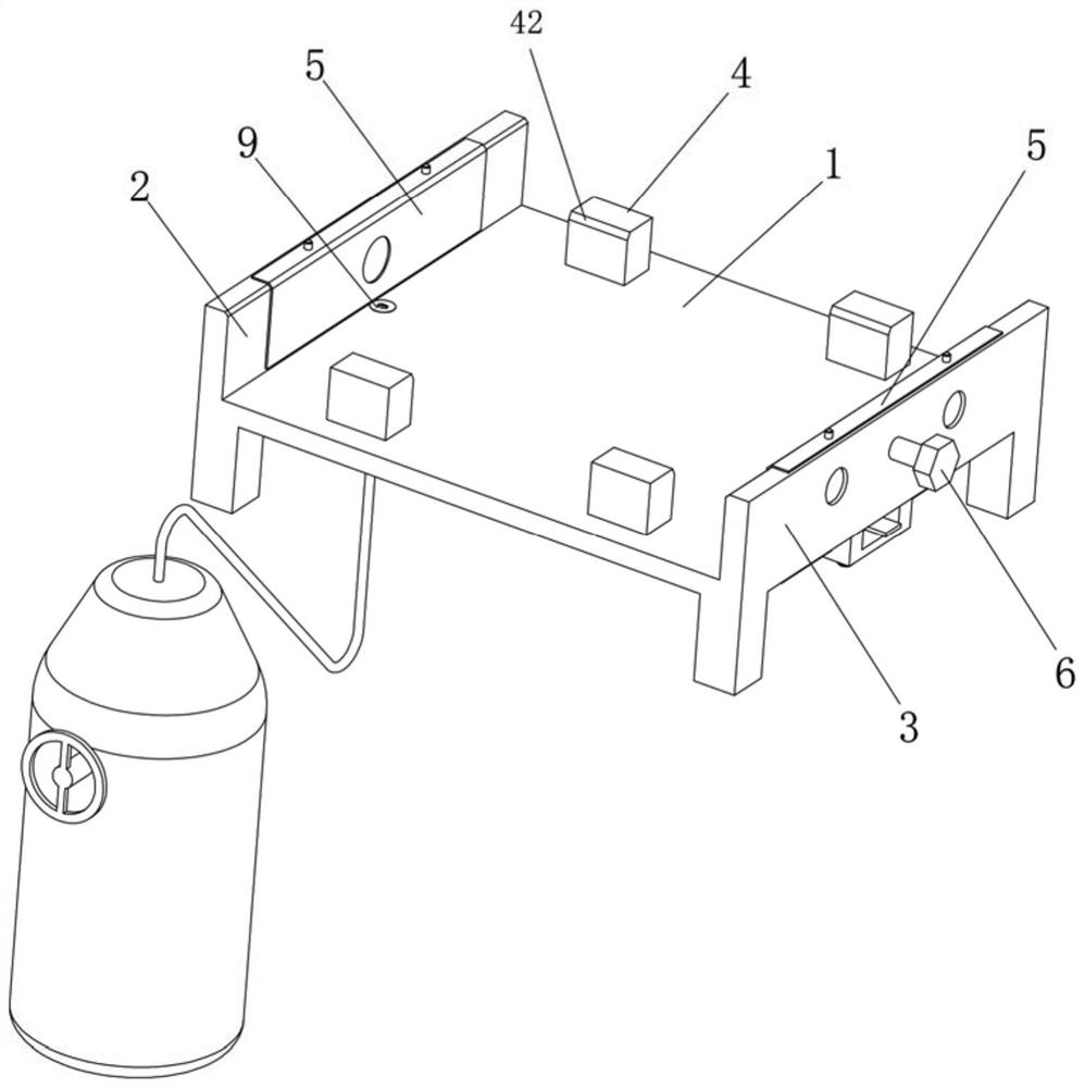
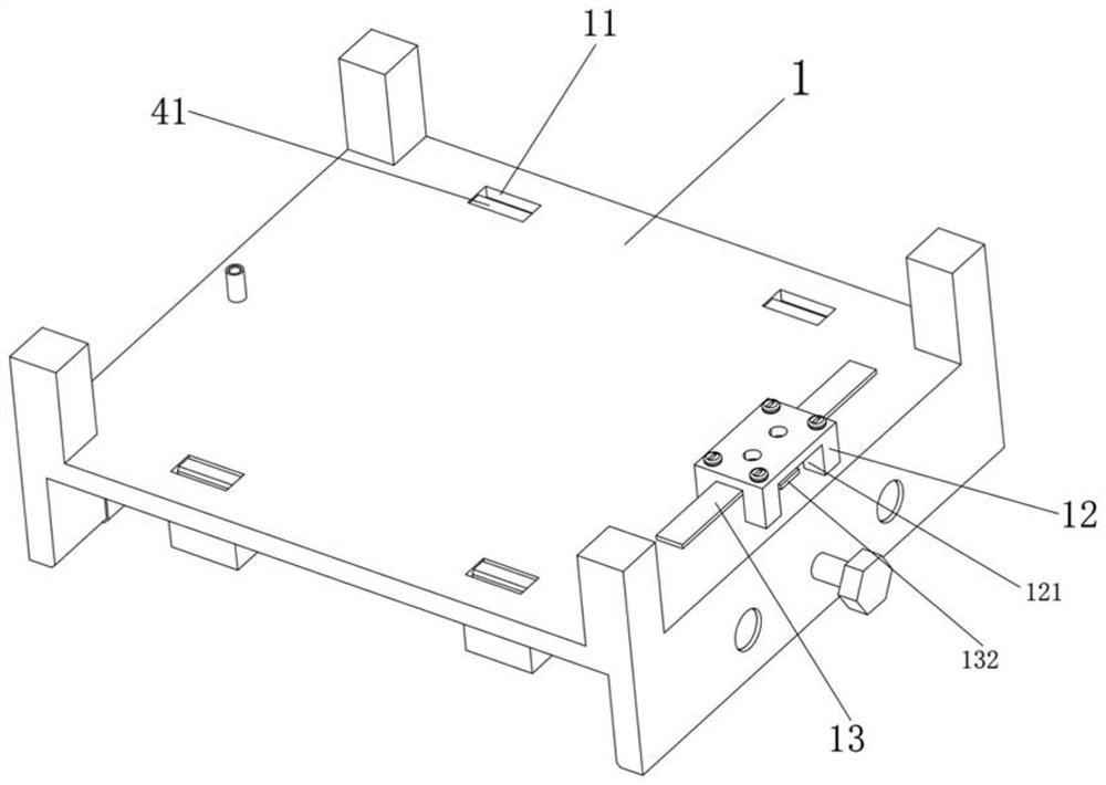
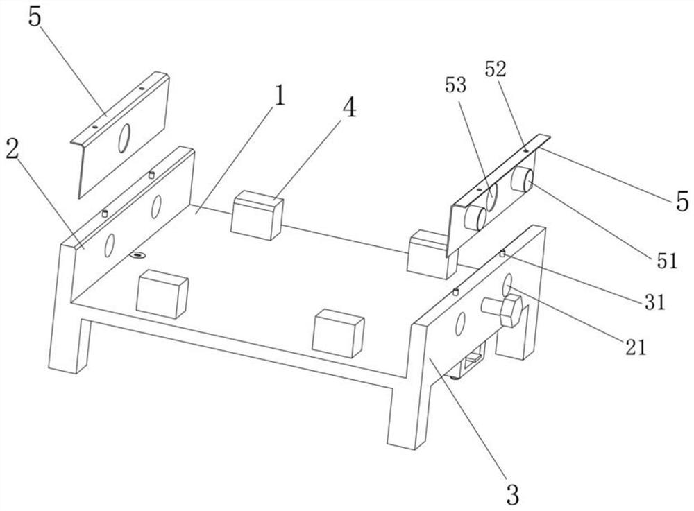
[0031] A low-cost and high-efficiency tooling structure for battery casing glue filling according to an embodiment of the present invention, such as Figure 1-Figure 6 As shown, it includes: a bottom plate 1, a left side plate 2 and a right side plate 3 are respectively formed on both sides of the bottom plate 1, and a number of limit blocks 4 are provided on the bottom plate 1 for limiting the position of the glue filling shell, There are four limit blocks 4, which limit the width direction of the glue filling shell; the bottom plate 1 is provided with an installation groove 11 that matches the limit block 4, and the bottom of the limit block 4 is provided with an installation groove 11 In conjunction with the buckle 41, a guide angle 42 is provided on the top...


PUM


Abstract

The invention relates to a low-cost and high-efficiency tool structure for battery shell glue filling. The low-cost and high-efficiency tool structure comprises a bottom plate, wherein a left side plate and a right side plate are formed on the two sides of the bottom plate correspondingly, a plurality of limiting blocks are arranged on the bottom plate, a side adjusting screw is in threaded connection with the right side plate in the transverse direction, one end of the side adjusting screw penetrates through the right side plate to be connected with a lining pad, and the left side of the bottom plate is connected with a glue inlet valve; the right side of the bottom plate is connected with a glue outlet valve, and a left air outlet hole and a right air outlet hole are formed in the glue outlet valve; and a support is arranged at the bottom of the bottom plate, a sealing pull strip is arranged on the support, the sealing pull strip is attached to the bottom end of the glue outlet valve, a pull strip hole is formed in the sealing pull strip, and the pull strip hole communicates with the left air outlet hole or the right air outlet hole. According to the low-cost and high-efficiency tool structure, through the tool automatic glue filling structure, the glue flowing speed of a glue inlet pipe is effectively adjusted, full filling glue is conveyed to a left glue filling loop and a right glue filling loop of a glue filling shell correspondingly, stable sealing of the glue is completed, and the consistency of glue filling is improved.

Description

technical field [0001] The invention relates to the field of storage battery energy, in particular to a low-cost and high-efficiency tooling structure for potting battery shells with glue. Background technique [0002] With the progress and development of society, the intelligentization of warehousing, family, travel, etc., the diversification of mobile consumer electronic products, and the battery as a provider of clean energy make it more and more sought after by consumers. Favored, become an integral part of electronic products. [0003] In the process of application, it can effectively improve the efficiency of glue filling, reduce the cost of glue filling, enhance the sealing stability of the system and the sealing consistency of glue filling; it will provide users with more peace of mind during use, improve user acceptance, and improve the reliability of the sealing structure. Sealing and glue filling efficiency are a very meaningful research topic. [0004] Usually,...

Claims


Application Information

Patent Timeline
Patent Type & Authority Applications(China)
IPC IPC(8): B05C13/02B05C11/10
CPCB05C13/02B05C11/10Y02P70/50
Inventor 张计中陈道戈杨庆宏邓通杭
Owner 飞毛腿能源科技有限公司
Learn More