Novel plasma stink treatment device

A plasma and odor technology, applied in the field of plasma odor control devices, to achieve the effect of accelerating flow, improving efficiency, and enhancing deodorization efficiency

Inactive Publication Date: 2013-09-18
BEIJING BODXY ENERGY CONSERVATION TECH & RES
View PDF5 Cites 0 Cited by
  • Summary
  • Abstract
  • Description
  • Claims
  • Application Information

AI Technical Summary

Problems solved by technology

[0005] The purpose of the present invention is to provide a plasma odor control device to solve the technical problem of effectively removing odor in an environment of normal temperature and pressure

Method used


Image

  • Novel plasma stink treatment device
  • Novel plasma stink treatment device
  • Novel plasma stink treatment device

Examples


Embodiment Construction

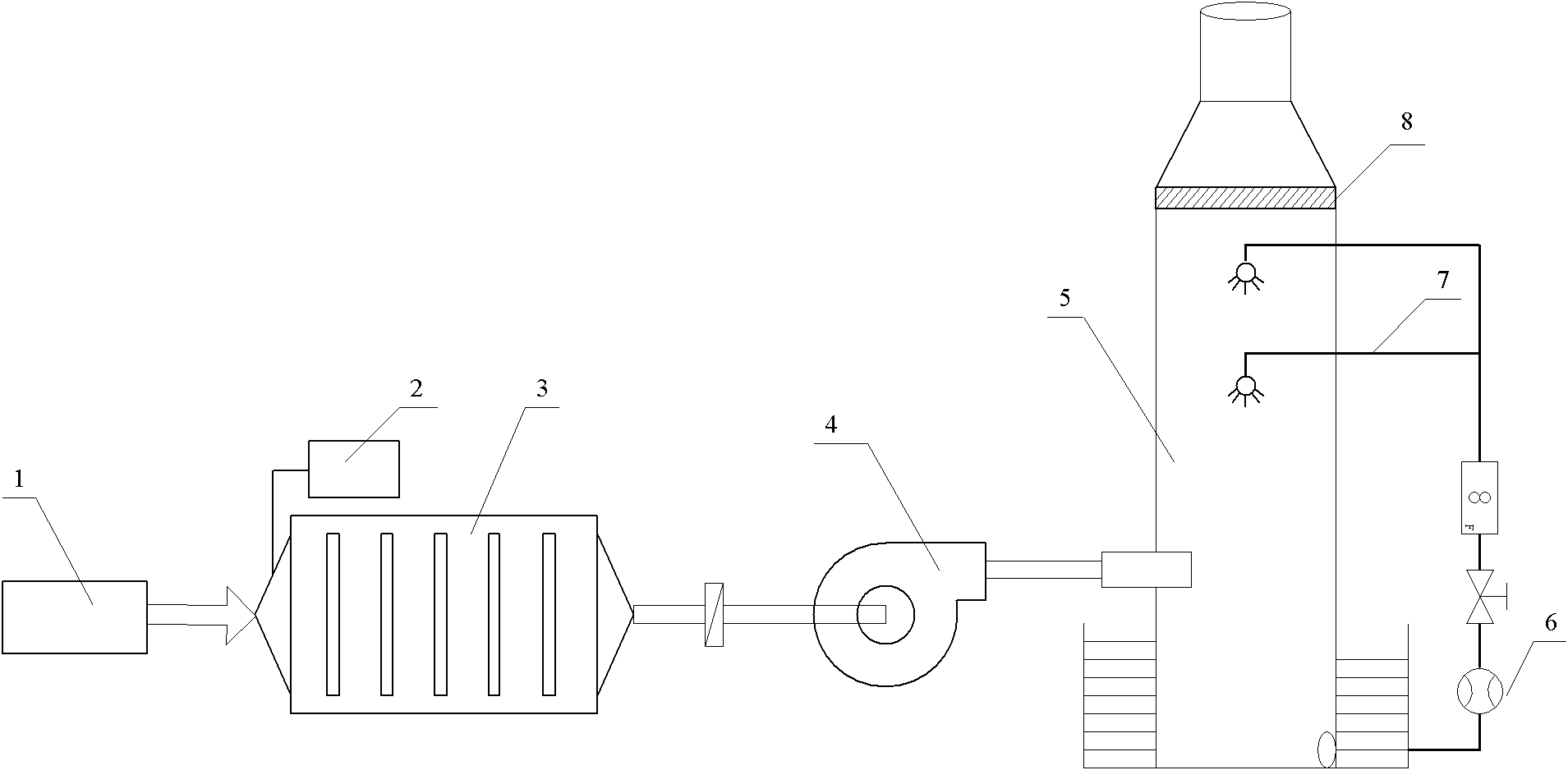
[0018] Structure of the present invention sees figure 1 , The device has an odor inlet 1, a power supply 2, a plasma deodorization reactor 3, a fan 4, a washing tower 5, a circulating pump 6, a spraying device 7, and a demisting device 8. The power supply can use a high-voltage pulse power supply, or a DC superimposed pulse power supply. Among them, the pulse peak voltage can be adjusted from 10 to 1000 kV, the rise time is between 1 and 100 nanoseconds, and the frequency is adjustable from 10-100 KHz, all of which can generate stable streamer discharge in the reactor.

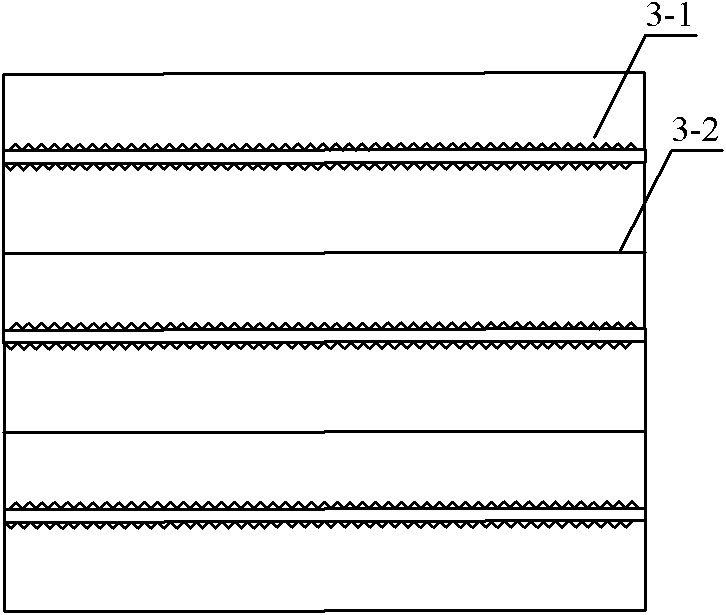
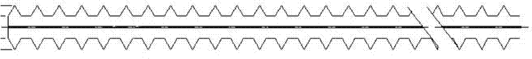
[0019] see figure 2 , wherein there are corona wire 3-1, pole plate 3-2. The deodorizing reactor 3 is composed of electrodes facing each other, one of which is composed of a number of corona wires 3-1 with serrations connected in parallel at equal distances, and the adjacent serrations on each corona wire 3-1 are misplaced. of. The corresponding electrode is a smooth pole plate 3-2, both of which are para...


PUM


Abstract

The invention discloses a plasma stink treatment device, which comprises a power supply, a plasma stink removal reactor, a fan and a washing tower, wherein the plasma stink removal reactor is connected with the washing tower. The device is characterized in that: the fan is positioned in a pipeline between the reactor and the washing tower; and an insulating material is connected to the joint of the reactor and the fan. The novel plasma stink treatment device has the characteristics of high efficiency, energy saving, environmental friendliness and the like.

Description

technical field [0001] The invention relates to a plasma stench control device. Background technique [0002] Malodorous gases mainly refer to all gaseous substances that stimulate the olfactory organs to cause people's unpleasantness and damage the living environment. The composition is particularly complex, including hydrogen sulfide, mercaptans, ammonia, amines, hydrocarbons, etc. It mainly comes from industrial production, municipal sewage, sludge treatment and garbage treatment facilities. These gases will cause varying degrees of damage to human breathing, digestion, cardiovascular, endocrine and nervous systems. Deodorization, in most cases, refers to the removal of pungent odorous gases mixed in the air, so that the discharged air quality can meet the requirements of the "Comprehensive Emission Standards of Air Pollutants" and "Emission Standards of Odor Pollutants" promulgated by the state. . [0003] Conventional deodorization technologies include absorption met...

Claims


Application Information

Patent Timeline
Patent Type & Authority Patents(China)
IPC IPC(8): A61L9/22
Inventor 姜学东王绪棠包晋榆宋宇朱翔苏超刘洋
Owner BEIJING BODXY ENERGY CONSERVATION TECH & RES
Why Eureka
Try Eureka