Automatic garlic screening machine
An automatic screening and garlic technology, which is applied in the direction of screening, solid separation, grille, etc., can solve the problems of low garlic screening efficiency, long consumption time, unsatisfactory garlic processing and packaging work requirements, etc., to meet the requirements of processing and packaging work, The effect of improving screening efficiency
- Summary
- Abstract
- Description
- Claims
- Application Information
AI Technical Summary
Problems solved by technology
Method used
Image

Examples
Embodiment Construction
[0056] In order to make the object, technical solution and advantages of the present invention clearer, the present invention will be further described in detail below in conjunction with the accompanying drawings and embodiments. It should be understood that the specific embodiments described here are only used to explain the present invention, not to limit the present invention.
[0057] The specific implementation of the present invention will be described in detail below in conjunction with specific embodiments.
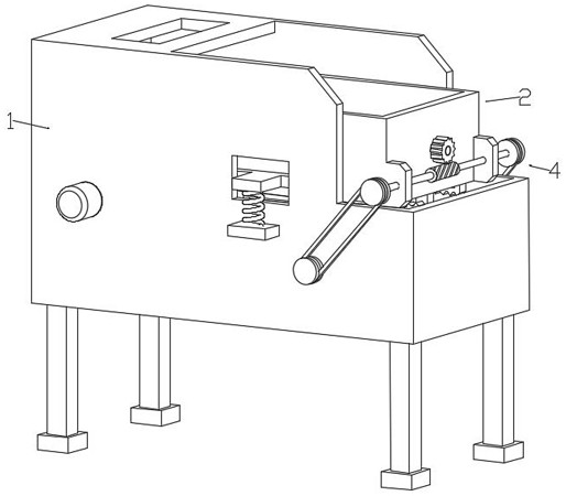
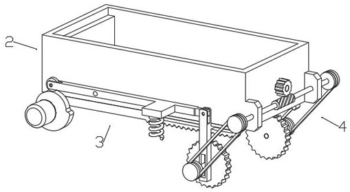
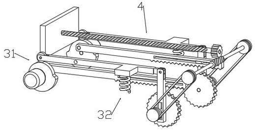
[0058] Such as figure 1 and figure 2 As shown, a kind of automatic garlic screening machine provided by the embodiment of the present invention includes a support box mechanism 1, a screening box mechanism 2, a screening shaking mechanism 3 and a garlic pushing mechanism 4, and the screening box mechanism 2 passes through the screening shaking mechanism 3 Installed in the support box mechanism 1, the garlic pushing mechanism 4 is installed between the screenin...
PUM
 Abstract
Description
Claims
Application Information