Quick remodeling mechanism for automobile part detection

A fast technology for auto parts, applied in the direction of vehicle testing, machine/structural component testing, measuring devices, etc., can solve problems such as limited service life of connecting parts, cumbersome operation steps, poor connection reliability of fixtures and testing equipment, etc. Achieve the effects of reasonable equipment structure design, fast and simple operation, and high efficiency of model change

Pending Publication Date: 2021-10-29
上海欧博自控技术装备有限公司
View PDF0 Cites 0 Cited by
  • Summary
  • Abstract
  • Description
  • Claims
  • Application Information

AI Technical Summary

Problems solved by technology

[0003] During the inspection of auto parts, fixtures are needed to clamp and fix them, but each type of fixture can usually only be used with one or several specific types of auto parts. For testing equipment that is shared by multiple products In other words, when the product is changed, it is necessary to replace the tooling fixture that matches the product, and the existing tooling fixture and testing equipment are screwed and connected by hexagonal screws. When disassembling or installing the tooling fixture, it is necessary to use professional tools to operate , the entire operation steps are cumbersome, time-consuming and labor-intensive, and due to the threaded connection, the service life of the connecting parts is limited, and in the installation, due to the differences in the operation of the operator, the installation of the hexagonal screws is too tight or too loose, resulting in tooling fixtures Poor connection reliability with testing equipment

Method used


Image

  • Quick remodeling mechanism for automobile part detection
  • Quick remodeling mechanism for automobile part detection
  • Quick remodeling mechanism for automobile part detection

Examples


Embodiment Construction

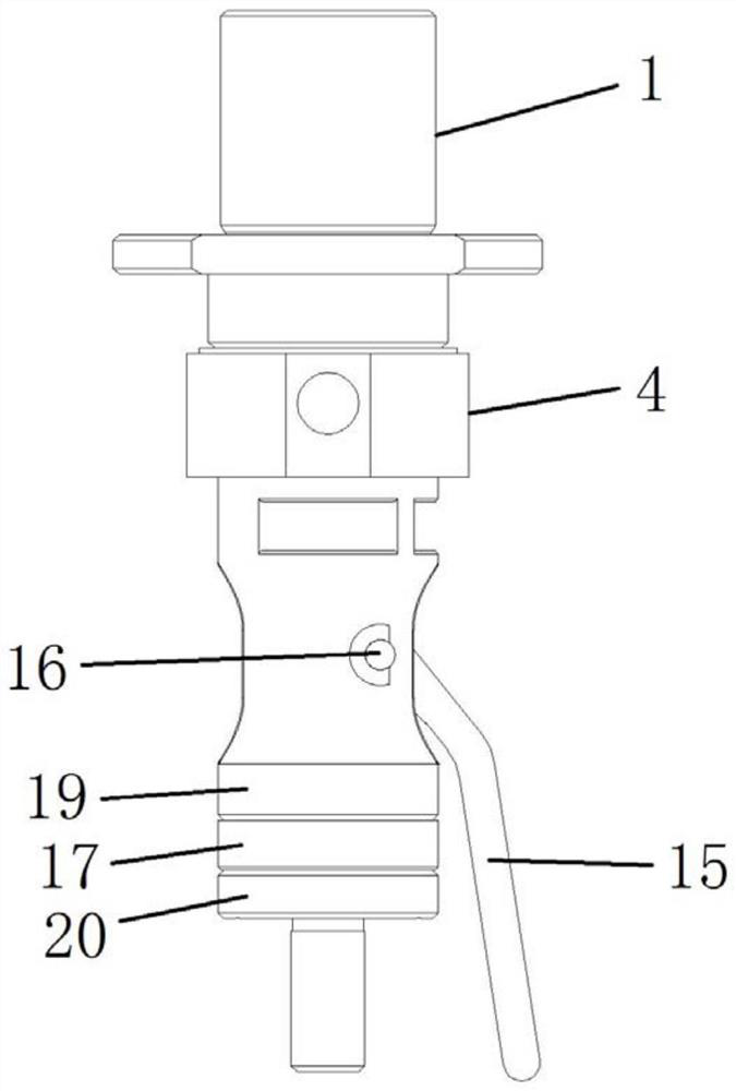
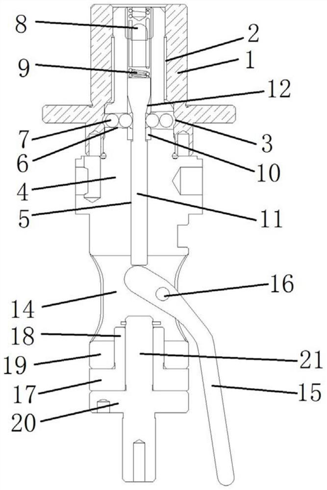
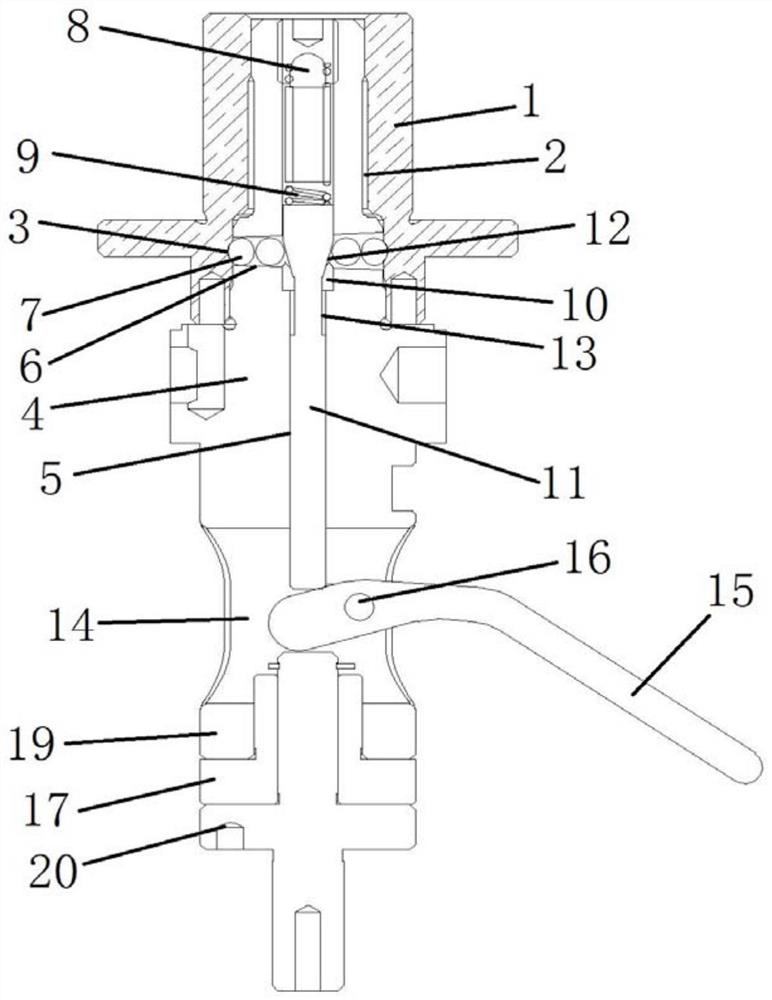
[0027] The embodiment of the present invention discloses a quick-change mechanism for auto parts detection, such as Figure 1 to Figure 6 As shown, it includes a fixed base 1, a guide sleeve 4, a beveled thimble 11, a positioning ball 7, a lifting drive device, a base 17 and a connecting shaft 20. The inside of the fixed base 1 is provided with a step-shaped installation hole 2 that penetrates along the axial direction, and the guide sleeve 4. The upper part is movably inserted into the installation hole 2, and the shape of the upper part of the guide sleeve 4 matches the shape of the installation hole 2. By setting the step-shaped installation hole 2, the guide sleeve 4 is limited when it is installed in the fixed seat 1. The side wall of the installation hole 2 is provided with an arc-shaped groove 3 along the circumferential direction, and the inside of the guide sleeve 4 is provided with a guide hole 5 along the axial direction. In the guide hole 5, a beveled thimble 11 is ...


PUM


Abstract

The invention discloses a quick remodeling mechanism for automobile part detection. Thequick remodeling mechanism comprises a fixed seat, a through step-shaped mounting hole is formed in the fixed seat along the axis direction, the upper part of a guide sleeve is movably inserted into the mounting hole, an arc-shaped groove is formed in the side wall of the mounting hole along the circumferential direction, and a guide hole is formed in the guide sleeve along the axis direction. A slope ejector pin is movably inserted in the guide hole, one end of the slope ejector pin is connected with a lifting driving device, a plurality of sliding through holes communicated with the guide hole are symmetrically formed in the upper portion of the guide sleeve in the radial direction, a plurality of positioning balls are movably arranged in each sliding through hole, and an inclined connecting face is arranged on the slope ejector pin. The inclined connecting face is driven by the lifting driving device to move to be right opposite to the sliding through holes, the inclined connecting face makes contact with the positioning balls located on the innermost side in the sliding through holes, part of the positioning balls located on the outermost side in the sliding through hole is embedded into the arc-shaped groove, and a base and a connecting shaft are sequentially installed at the bottom of the guide sleeve.

Description

technical field [0001] The invention relates to the technical field of equipment for testing auto parts, in particular to a quick changeover mechanism for testing auto parts. Background technique [0002] There are usually certain errors in the production process of auto parts on the production line, sometimes causing auto parts to fail to meet the standards. Therefore, quality inspection is required after the production and processing of auto parts. [0003] During the inspection of auto parts, fixtures are needed to clamp and fix them, but each type of fixture can usually only be used with one or several specific types of auto parts. For testing equipment that is shared by multiple products In other words, when the product is changed, it is necessary to replace the tooling fixture that matches the product, and the existing tooling fixture and testing equipment are screwed and connected by hexagonal screws. When disassembling or installing the tooling fixture, it is necessa...

Claims


Application Information

Patent Timeline
Patent Type & Authority Applications(China)
IPC IPC(8): G01M17/007B25B11/00
CPCG01M17/007B25B11/00
Inventor 薛冲鹿斌孙涛
Owner 上海欧博自控技术装备有限公司
Why Eureka
Try Eureka