Catheter handle and tip-deflectable steerable catheter

A technology for handles and catheters, which is applied in catheters, medical devices, and other medical devices. It can solve problems such as damaged tube parts, impaired fluid flow, and inability to ensure gaps, so as to avoid contact and prevent abnormal noise.

Active Publication Date: 2021-10-29
JAPAN LIFELINE CO LTD
View PDF10 Cites 0 Cited by
  • Summary
  • Abstract
  • Description
  • Claims
  • Application Information

AI Technical Summary

Problems solved by technology

[0015] However, in the catheter handle described in Patent Document 3, there is no gap between the handle main body 331 and the rotating plate 3320 through which the tube member can pass.
Assuming that even if a gap through which the pipe member can pass is ensured between the handle main body 331 and the rotating plate 3320 , when the pipe member extending from the lumen opened on the other side of the rotating plate 3320 passes through one side of the rotating plate 3320 In the case of the above-mentioned gap between the handle body 331 and the handle body 331, it is considered that the pipe member is twisted due to the difference in height, the flow of the fluid is impaired, or the pipe member is damaged.

Method used


Image

  • Catheter handle and tip-deflectable steerable catheter
  • Catheter handle and tip-deflectable steerable catheter
  • Catheter handle and tip-deflectable steerable catheter

Examples


Embodiment Construction

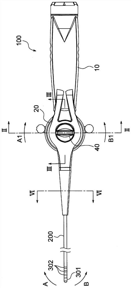
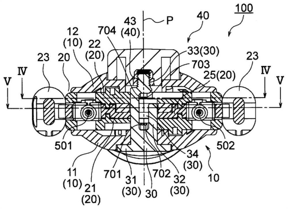
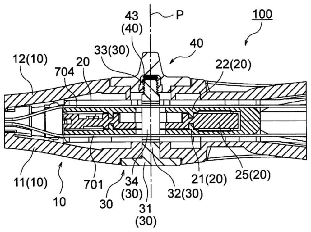
[0063] Figure 1 to Figure 7 The handle 100 of this embodiment shown is a handle that is attached to the proximal end side of a catheter shaft 200 with a multi-lumen structure to form an electrode catheter (a catheter whose tip can be deflected). A handle part 11 is combined with the second handle part 12; the rotary operation part 20 is disposed between the first handle part 11 and the second handle part 12 and has a rotation axis ( P) A freely rotatable disc-shaped rotating plate 25 to which a first operation cable 501 and a second operation cable 502 are connected for deflecting the distal end of the catheter shaft 200 in the first direction and the second direction, respectively. Each base end; an adjustment pin 30 having a base portion 31 fixed to the first handle member 11, a shaft portion 32 arranged to penetrate the rotating plate 25 along the rotation axis (P), and a shaft portion 32 formed on the front end side of the shaft portion 32. External threaded portion 33; ...


PUM


Abstract

The purpose of the present invention is to provide a handle capable of making the amount of operating wire drawn sufficiently long and capable of inserting a tube part extending from a lumen of a catheter shaft into the inside of a handle body without contacting a rotary plate or the operating wire. The handle (100) of the present invention is provided with a handle body (10), comprising a first handle member (11) and a second handle member (12), and a rotary operation part (20); the rotary operation part is provided with a rotary plate (25), a first spacer member (21) mounted non-rotatably on the handle body, and a second spacer member (22) mounted non-rotatably on the handle body; the rotary plate has a guide rail (251) that prescribes the route of the operating wires (501, 502) in the rotary operation part so as to detour along the circumferential direction of the rotary plate; and guide passages (211, 221) for tube parts are formed in each of the first spacer member and the second spacer member.

Description

technical field [0001] The invention relates to a catheter handle and a catheter whose front end can be deflected. Background technique [0002] A medical catheter is generally configured such that a handle is attached to the base end (proximal end) side of the catheter shaft. [0003] As the catheter handle, various catheter handles have been proposed depending on the type of catheter. For example, there are cases where it is desired to bend or extend the distal end portion (distal end) of the catheter by manipulating the handle for the catheter. In this way, as a mechanism for deflecting the front end portion of the catheter for operation on the hand side, the following mechanism has been introduced: the base end of the operation cable is connected to the rotating plate installed to be rotatable relative to the handle main body. The rotating plate is rotated to change (deflect) the direction of the distal end of the catheter (see Patent Document 1 below). [0004] In ad...

Claims


Application Information

Patent Timeline
Patent Type & Authority Applications(China)
IPC IPC(8): A61M25/092A61M25/01
CPCA61M25/0136A61M25/0147A61M2205/0216
Inventor 渡部贵史
Owner JAPAN LIFELINE CO LTD
Why Eureka
Try Eureka