Cleaning method of cleaning tool

A technology for cleaning tools and support bases, which is applied to cleaning equipment, cleaning machinery, carpet cleaning, etc., can solve the problems of the mop head structure, the complex structure of the mop head and the mop bucket, and the high production cost, so as to simplify the scraping structure and simplify the operation. Simple, clear-cut effects

Active Publication Date: 2021-11-02
张青青
View PDF7 Cites 0 Cited by
  • Summary
  • Abstract
  • Description
  • Claims
  • Application Information

AI Technical Summary

Problems solved by technology

The above-mentioned method uses the rotational force of the mop rod to change the traditional way of squeezing the wiper relative to the moving scraper, so that the operator is more labor-saving, but the mop bucket structure, mop head structure, mop head and mop bucket of the above-mentioned method The matching structure is extremely complex and the production cost is high

Method used


Image

  • Cleaning method of cleaning tool
  • Cleaning method of cleaning tool
  • Cleaning method of cleaning tool

Examples


Embodiment Construction

[0047] Below in conjunction with accompanying drawing, the present invention will be further described with specific embodiment, see Figure 1-19 Shown:

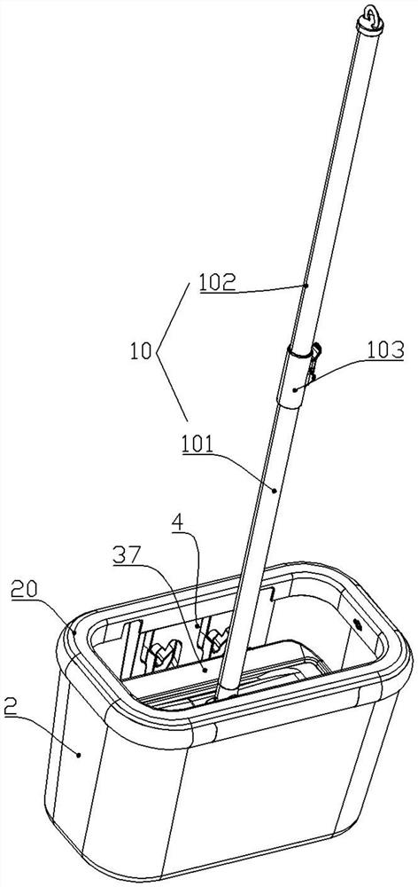
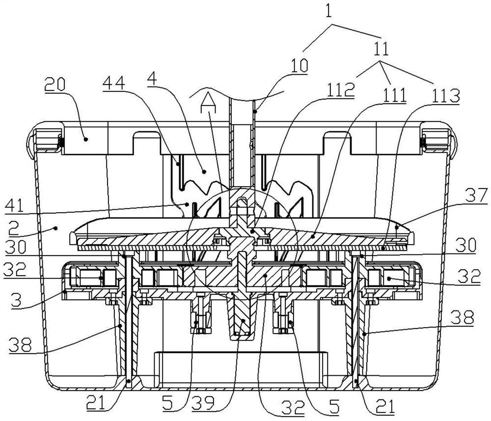
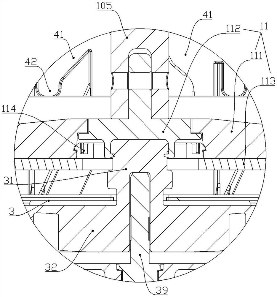
[0048] A cleaning method for cleaning tools, comprising a mop 1 and a mop bucket 2, the mop 1 includes a mop rod 10, a rotatable mop head 11 connected to the mop rod 10, the mop head 11 is provided with a wiper 113, the mop head The rotation method of 11 can adopt the realization method in the prior art: as Chinese Patent No. CN2010202394946, the mop rod 10 at least includes the first rod body 101 and the second rod body 102 which are nested in each other, and the first rod body 101 and the second rod body 102 pass through the internal The screw rod is driven to convert the telescopic motion between the first rod body 101 and the second rod body 102 into the rotation motion of the first rod body 101 , and the mop head 11 is hinged on the lower end of the first rod body 101 . Of course, other ways can also be used to realize...


PUM


Abstract

The invention belongs to the technical field of cleaning tools, and particularly relates to a cleaning method of a cleaning tool, and the cleaning method of a mop comprises the following steps: firstly, the mop is arranged, a mop head is placed on a supporting seat in a direction that a wiping object faces downwards, and a hinge seat abuts against a positioning seat; during cleaning, the supporting seat is kept at the low position of a mop bucket, the hinge seat is rotated, and the scraper conducts rotary scraping washing on the wiping object below a mop head body; during squeezing, the supporting seat is kept at the high position of the mop bucket, the hinge seat is rotated, and the scraper is used for rotationally squeezing the wiping object below the mop head body; finally, the mop is pulled upwards, the mop head is taken down from the supporting seat. According to the cleaning method of the cleaning tool, the structure is simple and stable, and the operation is convenient and fast.

Description

technical field [0001] The invention belongs to the technical field of cleaning tools, in particular to a cleaning method for cleaning tools. Background technique [0002] Mops are a necessity in daily life, and more and more mops appear on the market, but the flat mop is still the mainstream product, and its advantage of having a large wiping surface is widely recognized. Centrifugal spin dehydration cleaning tools have appeared on the market, such as Chinese patent CN201320830364.3, the cleaning tool and its rotary mop, which adopts a pressure-rotating mop rod, and after the mop head is suspended in the air, press down on the mop rod to make The wipes on the mop head are centrifugally dehydrated; or, as in Chinese patent CN 201621152336.0, when dehydrating, it is necessary to bend the two ends of the mop head first and then place it in the dehydration area of ​​the mop bucket, and press down the mop rod so that the mop head The wipes were centrifuged. The above-mentioned...

Claims


Application Information

Patent Timeline
Patent Type & Authority Applications(China)
IPC IPC(8): A47L13/58A47L13/256
CPCA47L13/58A47L13/256
Inventor 张青青
Owner 张青青
Why Eureka
Try Eureka