
Reflux defoaming device for electroplating process tank

A technology of electroplating process and defoaming device, which is applied in the direction of foam dispersion/prevention, etc., and can solve the problems that cannot meet the processing requirements of defoaming, and the effect of defoaming is not good.

Active Publication Date: 2021-12-14
SHANDONG YANGCHENG BIOLOGY TECH CO LTD
View PDF10 Cites 0 Cited by
  • Summary
  • Abstract
  • Description
  • Claims
  • Application Information

AI Technical Summary

Problems solved by technology

[0005] The purpose of the embodiments of the present invention is to provide a reflux defoaming device for the electroplating process tank, which aims to solve the problem that the existing electrophoresis tank uses a filter screen with a single structure for defoaming treatment, which leads to a poor effect of defoaming and cannot Problems with meeting current processing requirements for defoaming

Method used


Image

  • Reflux defoaming device for electroplating process tank
  • Reflux defoaming device for electroplating process tank
  • Reflux defoaming device for electroplating process tank

Examples


Embodiment Construction

[0028] In order to make the object, technical solution and advantages of the present invention clearer, the present invention will be further described in detail below in conjunction with the accompanying drawings and embodiments. It should be understood that the specific embodiments described here are only used to explain the present invention, not to limit the present invention. The specific implementation of the present invention will be described in detail below in conjunction with specific embodiments.

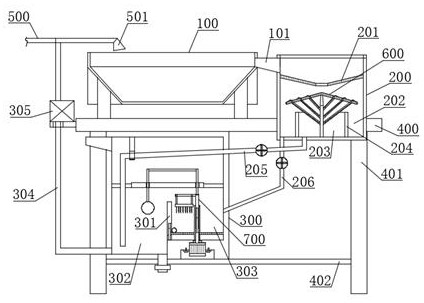
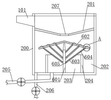
[0029] like figure 1 As shown, in a preferred embodiment provided by the present invention, the reflux defoaming device of the electroplating process tank is provided, and the device includes the electrophoresis tank 100, the first defoaming box 200 and the second defoaming box 300, and the electrophoresis tank The upper part of the tank 100 has an overflow port 101, the electrophoresis tank 100 is connected to the first defoaming box 200 through the overflow port 101, a...


PUM


Abstract

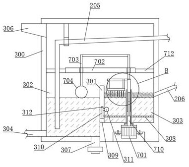
The embodiment of the present invention is applicable to the technical field of electroplating and coating, and provides a reflux defoaming device for an electroplating process tank, including an electrophoresis tank, a first defoaming box, and a second defoaming box. The upper part of the electrophoresis tank has an overflow port, so The electrophoresis tank is connected to the first defoaming tank through an overflow port; the lower inner cavity of the first defoaming tank is separated by an annular partition to form an outer ring cavity and an inner circular cavity, and the inner cavity of the first defoaming tank A first defoaming assembly is also provided; the inner cavity of the second defoaming box is separated by a partition to form two chambers, the first chamber and the second chamber, and the bottom of the second chamber is higher than the first chamber. A bottom of the chamber; and the second chamber communicates with the first chamber through a connecting channel opened on the partition; a second defoaming assembly is arranged on the upper part of the second chamber. The embodiments of the present invention can solve the problem that the defoaming effect of the existing electrophoresis tank is not good and cannot meet the current processing requirements for defoaming.

Description

technical field [0001] The embodiment of the invention belongs to the technical field of electroplating and coating, and in particular relates to a reflow defoaming device for an electroplating process tank. Background technique [0002] Electroplating coating is a commonly used technical method for the post-processing of parts such as automobiles, aviation, and ships. Electrophoretic coating is a special coating film forming method. It is the most practical construction process for water-based coatings. It has the characteristics of water solubility, non-toxicity and easy automatic control. It is rapidly used in industries such as ships, automobiles, building materials, hardware and home appliances. be widely used. [0003] In the electrophoretic coating of ship parts, because the UF liquid in the UF tank for cleaning ship parts contains low-molecular resin, the air in the UF liquid will easily cause a lot of foam in the UF liquid during the cleaning process. In severe cas...

Claims


Application Information

Patent Timeline
Patent Type & Authority Patents(China)
IPC IPC(8): B01D19/02
CPCB01D19/02
Inventor 王东阳王传敬戈连峰
Owner SHANDONG YANGCHENG BIOLOGY TECH CO LTD
Learn More