Developing tank automatic defoaming device

A defoaming device and automatic technology are applied in the field of developing machines, which can solve the problems of waste of cost by manufacturers, failure to achieve defoaming effect, oil spots, etc., and achieve the effects of low production cost and simple structure.

Inactive Publication Date: 2012-11-21
昆山华新电子集团有限公司
View PDF0 Cites 0 Cited by
  • Summary
  • Abstract
  • Description
  • Claims
  • Application Information

AI Technical Summary

Problems solved by technology

However, when the amount added is small, the defoaming effect will not be achieved; when the amount is excessively added, oil spots will appear, and it will cause a certain amount of cost waste to the manufacturer

Method used


Image

  • Developing tank automatic defoaming device

Examples


Embodiment Construction

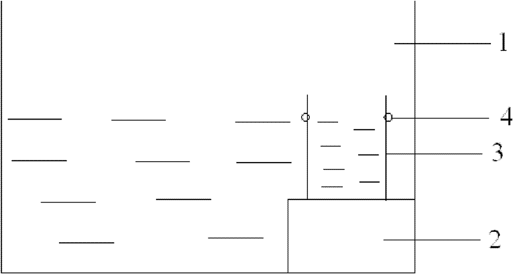
[0009] Refer to the attached figure 1 Embodiments of the present invention will be described in detail.

[0010] The developing tank automatic defoaming device of the present invention comprises a developing tank 1 and an auxiliary tank 2 in the developing tank, and a defoaming container 3 is positioned in the developing tank 1, and in the present embodiment, the defoaming container is a glass vessel, in which Defoamer, the upper end of defoaming container 3 is provided with some holes 4, and the distance between described hole 4 and the bottom end of developing tank 1, just can be the height that the foam in developing tank 1 flows into defoaming container 3, when containing foam like this When the developing solution reaches this height, it can automatically flow into the glassware where the defoamer is placed, so as to achieve the defoaming effect.

[0011] In this embodiment, the defoaming container 3 is positioned on the end surface of the auxiliary tank 2; and the holes...


PUM


Abstract

The invention discloses a developing tank automatic defoaming device. The automatic defoaming device comprises a developing tank and an auxiliary tank in the developing tank. According to the automatic defoaming device, the upper end of the auxiliary tank arranged in the developing tank is provided with a defoaming container containing a defoaming agent, the upper end of the defoaming container is provided with a plurality of apertures, and the distance between the apertures and the bottom end of the developing tank equals to the height enabling the foam in the developing tank flows into the defoaming container, so the foams contained in a developing liquid can automatically flow into the defoaming container provided with the defoaming agent when the developing liquid reaches the height, thereby a defoaming effect is realized. The device has the advantages of simple structure and low manufacturing cost.

Description

technical field [0001] The invention relates to the field of developing machines, and specifically provides an automatic defoaming device for a developing tank. Background technique [0002] The dry film process in the production process of printed circuit boards is to remove the unexposed dry film by developing. The dry film is photosensitive insulating resin, and the developing solution is 0.9%-1.5% sodium carbonate solution. Due to the continuous dissolution of the dry film, the developer produces a certain amount of foam during the system circulation spraying process, and the foam will affect the quality of the development to a certain extent, causing inconvenience to production. Therefore, in industrial production, it is often necessary to manually add a certain amount of defoamer every two hours to suppress the generation of foam. However, when the amount added is small, the defoaming effect cannot be achieved; when the amount is excessively added, oil spots will app...

Claims


Application Information

Patent Timeline
IPC IPC(8): G03F7/30
Inventor 张安好
Owner 昆山华新电子集团有限公司
Why Eureka
Try Eureka