Drawing die and drawing method for micro tube

A technology of microtubes and molds, applied in the direction of metal extrusion molds, etc., can solve the problems of many drawing passes, multiple annealing times, and large drawing force, so as to improve drawing efficiency, reduce drawing passes, increase The effect of large amount of deformation

Pending Publication Date: 2021-11-02
NORTHWESTERN POLYTECHNICAL UNIV
View PDF8 Cites 0 Cited by
  • Summary
  • Abstract
  • Description
  • Claims
  • Application Information

AI Technical Summary

Problems solved by technology

[0002] Now, the frictional force accounts for a large proportion in the drawing process of the microtube, which leads to a large drawing force, the pipe is easy to break during the drawing process, the amount of deformation per pass is limited, there are many drawing passes, and the number of annealing between passes is large; the middle Requires multiple heat treatments, low efficiency and high cost

Method used


Image

  • Drawing die and drawing method for micro tube
  • Drawing die and drawing method for micro tube
  • Drawing die and drawing method for micro tube

Examples


Embodiment Construction

[0030] Exemplary embodiments of the present disclosure will be described in more detail below with reference to the accompanying drawings. Although exemplary embodiments of the present disclosure are shown in the drawings, it should be understood that the present disclosure may be embodied in various forms and should not be limited by the embodiments set forth herein. Rather, these embodiments are provided for more thorough understanding of the present disclosure and to fully convey the scope of the present disclosure to those skilled in the art.

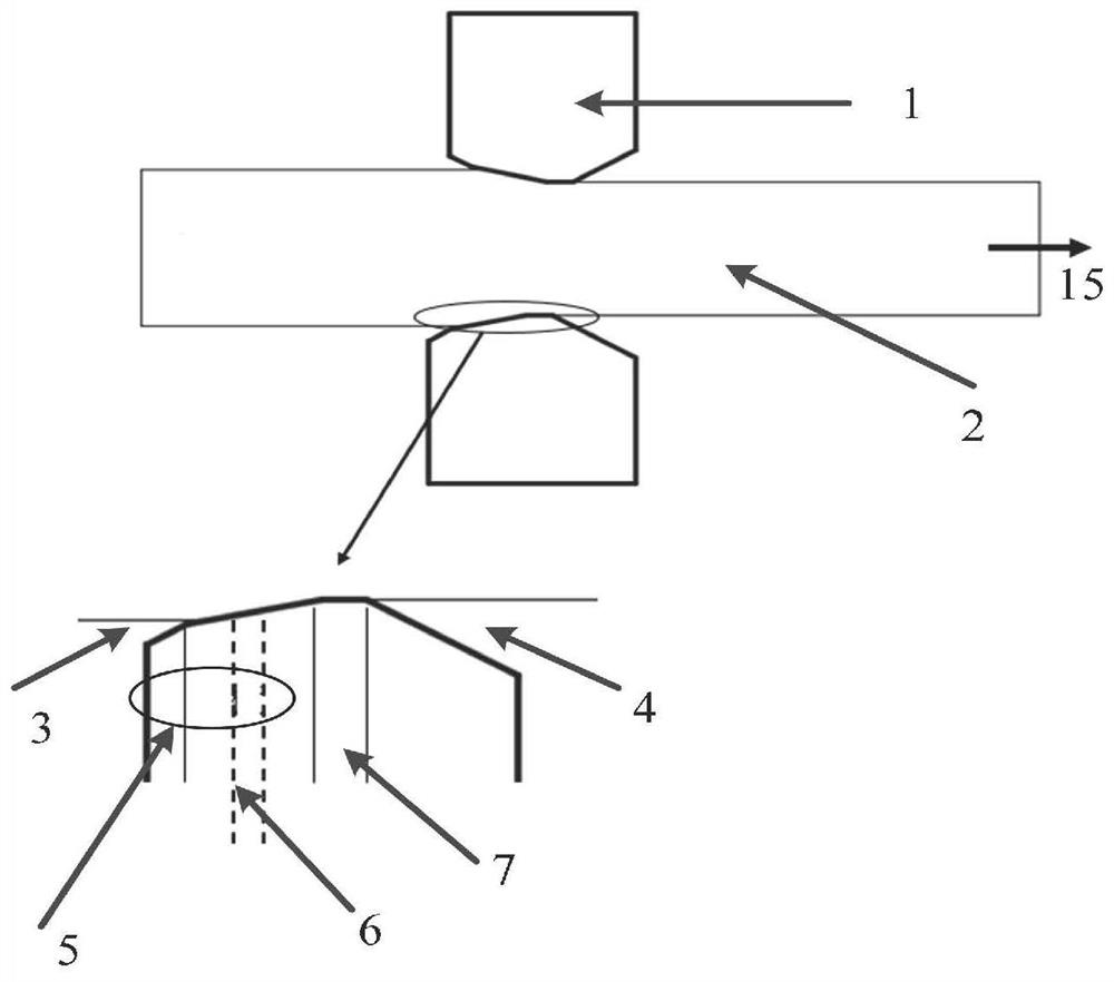
[0031] Such as figure 1 As shown, the embodiment of the present invention proposes a drawing die for micro-pipes, the die includes: a drawing die main body 1, and one end of the drawing die main body 1 is provided with a pipe material inlet 3, which is connected with the inlet 3. A pipe material outlet 4 is symmetrically arranged; a drawing channel connecting the material inlet 3 and the material outlet 4 is provided, and a tapered...


PUM


Abstract

The invention provides a drawing die and a drawing method for a micro tube, and the drawing die comprises a drawing die main body, one end of the drawing die main body is provided with a tube feeding port, and a tube discharging port is formed symmetrically with the tube feeding port; the drawing die further comprises a drawing channel communicating with the feeding port and the discharging port, and a conical surface area close to the feeding port is arranged on the drawing channel; an annular oil groove or N oil injection holes are formed in the conical surface area, and N is larger than or equal to 1; and a tube is extruded and lubricated by injecting oil into the annular oil groove or the oil injection holes. According to the drawing device and the drawing method provided by the invention, the single-pass deformation of the tube can be improved, the drawing passes are reduced, and the drawing efficiency is improved.

Description

technical field [0001] The invention relates to the technical field of precision machining of metal pipes, in particular to a drawing die and a drawing method for fine pipes. Background technique [0002] At present, the frictional force accounts for a large proportion in the drawing process of the microtube, which leads to a large drawing force, the pipe is easy to break during the drawing process, the amount of deformation per pass is limited, there are many drawing passes, and the number of annealing between passes is large; Multiple heat treatments are required, resulting in low efficiency and high cost. [0003] The area where the deformation occurs during the drawing process is mainly concentrated in the cone area, and the wall and diameter reduction of the pipe occurs. This area is mainly subjected to the drawing force, the positive pressure of the cone area on the pipe, and the outer wall of the pipe and the mold. Friction, if it is drawn with a mandrel, there is al...

Claims


Application Information

Patent Timeline
Patent Type & Authority Applications(China)
IPC IPC(8): B21C23/08B21C23/32B21C25/02
CPCB21C23/085B21C23/32B21C25/02
Inventor 李恒韩廷状张铎赵梦月王峥杨许冬
Owner NORTHWESTERN POLYTECHNICAL UNIV
Why Eureka
Try Eureka