Rapid stamping device for metal handicraft machining and method

A technology for stamping devices and handicrafts, applied in metal processing equipment, peeling devices, forming tools, etc., can solve the problems of poor control of lubricating oil smearing amount, poor lubrication effect, troublesome replacement of workpiece materials, etc. Influence, improve smear effect, practical effect

Active Publication Date: 2021-11-02
中山市硕荣精密科技有限公司
View PDF9 Cites 5 Cited by
  • Summary
  • Abstract
  • Description
  • Claims
  • Application Information

AI Technical Summary

Problems solved by technology

During the stamping process, it is necessary to fix the metal plate and apply lubricating oil. On the one hand, the amount of lubricating oil applied is not easy to control, and excessive lubricating oil will cause environmental pollution during the transfer process; on the other hand, it is relatively difficult to replace the processed workpiece material. Trouble, in view of the above problems, the existing patent announcement number is CN111604427B patent has announced a stamping device, the device uses a transmission method, so that the device can self-supply oil when stamping, but this oil supply method can not give the surface of the workpiece Evenly oiled, so the actual lubrication effect is not very good, and the above-mentioned processing method needs to be unloaded after processing, which takes up subsequent processing time. Based on this, a fast stamping device and method for processing metal crafts are now provided.

Method used


Image

  • Rapid stamping device for metal handicraft machining and method
  • Rapid stamping device for metal handicraft machining and method
  • Rapid stamping device for metal handicraft machining and method

Examples


Embodiment 1

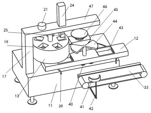
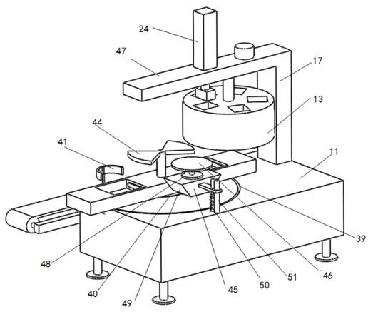
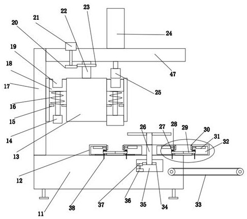
[0028] see Figure 1-6 , in an embodiment of the present invention, a quick stamping device for processing metal crafts, comprising a base 11 and several legs arranged at its lower end, the upper end of the base 11 is provided with an upper mold assembly for quick stamping of metal parts, The upper mold assembly includes a column 17 connected to the upper end of the base 11 and a mounting horizontal plate 47 arranged on the upper end of the column 17. The upper end of the mounting horizontal plate 47 is equipped with a lifting push rod 24, and the output end of the lifting push rod 24 There is a docking block 25, and the mounting horizontal plate 47 is provided with stamping parts that cooperate with the docking block 25 and are used to switch punching heads;

[0029] The upper end of the base 11 is provided with a lower mold assembly matched with the upper mold assembly, the lower mold assembly includes a clamping seat 12, and two sides of the upper end of the clamping seat 1...


PUM


Abstract

The invention discloses a rapid stamping device for metal handicraft machining and a method. The rapid stamping device comprises a base and a plurality of supporting legs arranged at the lower end of the base, an upper die assembly used for rapidly stamping a metal part is arranged at the upper end of the base, the upper die assembly comprises a stand column connected with the upper end of the base and a mounting transverse plate arranged at the upper end of the stand column, a lifting push rod is mounted at the upper end of the mounting transverse plate, a butt joint insertion block is arranged at the output end of the lifting push rod, and a stamping part matched with the butt joint insertion block and used for switching stamping heads is arranged on the mounting transverse plate; and the upper end of the base is provided with a lower die assembly matched with the upper die assembly. According to the rapid stamping device, the design is conducted aiming at the defects of an existing device, feeding operation and punching operation are separated by arranging a double-station switching mode, and therefore the problem that working procedures influence one another is avoided, and the machining efficiency is improved; and different punches can be switched according to the requirements aiming at the handicraft machining requirements, so that frequent manual replacement is not needed, and the machining efficiency is ensured.

Description

technical field [0001] The invention relates to the technical field of metal handicraft processing, in particular to a fast stamping device and method for metal handicraft processing. Background technique [0002] Metal crafts need to extrude and deform metal during processing, especially when processing metal sheets, which have different requirements in different environments. In order to meet special needs, workers need to treat the plates differently. Metal stamping is to change the metal plate into a three-dimensional shape through the stamping die. Generally, the metal plate is placed between the stamping head and the die for extrusion, so that the metal plate is deformed. During the stamping process, it is necessary to fix the metal plate and apply lubricating oil. On the one hand, the amount of lubricating oil applied is not easy to control, and excessive lubricating oil will cause environmental pollution during the transfer process; on the other hand, it is relative...

Claims


Application Information

Patent Timeline
Patent Type & Authority Applications(China)
IPC IPC(8): B21D22/02B21D37/18B21D45/06
CPCB21D22/02B21D37/18B21D45/06
Inventor 陈瑞琴
Owner 中山市硕荣精密科技有限公司
Why Eureka
Try Eureka