Annular welding equipment of valve base for valve production

A ring welding and valve technology, applied in welding equipment, auxiliary welding equipment, welding/cutting auxiliary equipment, etc., can solve the problems of increasing the workload of the staff, increasing the cost of the enterprise, wasting working time, etc., to achieve continuous welding production, Reduce the difficulty of work and avoid the effect of automatic prolapse

Pending Publication Date: 2021-11-02
段宏海
View PDF0 Cites 0 Cited by
  • Summary
  • Abstract
  • Description
  • Claims
  • Application Information

AI Technical Summary

Problems solved by technology

[0004] The object of the present invention is to provide a valve base annular welding equipment for valve production, to solve the problem that the valve base itself does not have any tight structure in the background technology, and because its function is only for fixing, it makes itself and the base There is no need for tight welding at the joints that fit together, so that most of the small valves are welded manually by the staff, which undoubtedly increases the workload of the staff. Technology waste increases the cost of the enterprise. If the traditional annular welding device is used for welding, the valve needs to be loaded and dropped only, resulting in a waste of working time and poor continuous production effect.

Method used


Image

  • Annular welding equipment of valve base for valve production
  • Annular welding equipment of valve base for valve production
  • Annular welding equipment of valve base for valve production

Examples


Embodiment Construction

[0032] The following will clearly and completely describe the technical solutions in the embodiments of the present invention with reference to the accompanying drawings in the embodiments of the present invention. Obviously, the described embodiments are only some, not all, embodiments of the present invention. Based on the embodiments of the present invention, all other embodiments obtained by persons of ordinary skill in the art without making creative efforts belong to the protection scope of the present invention.

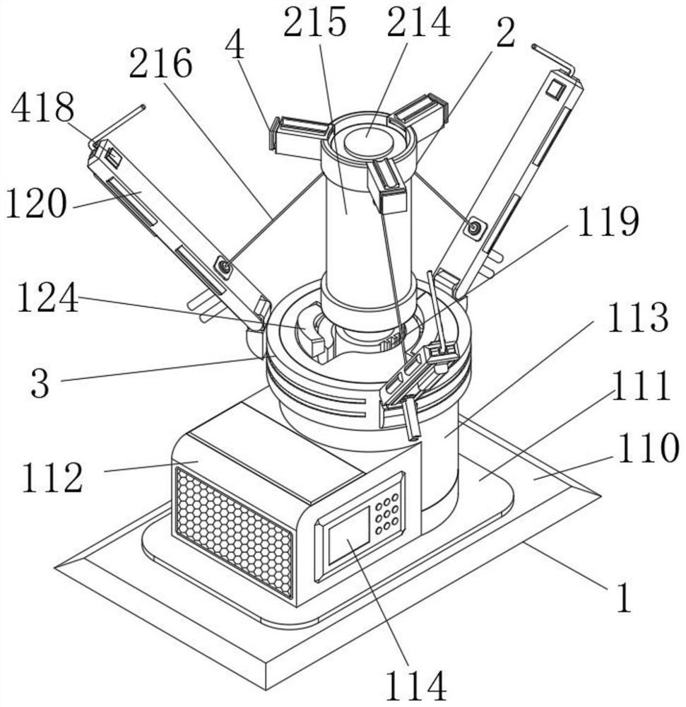
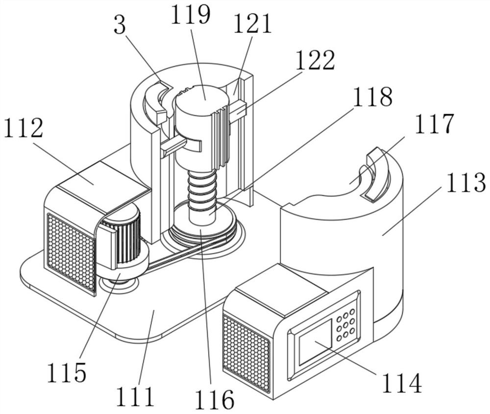
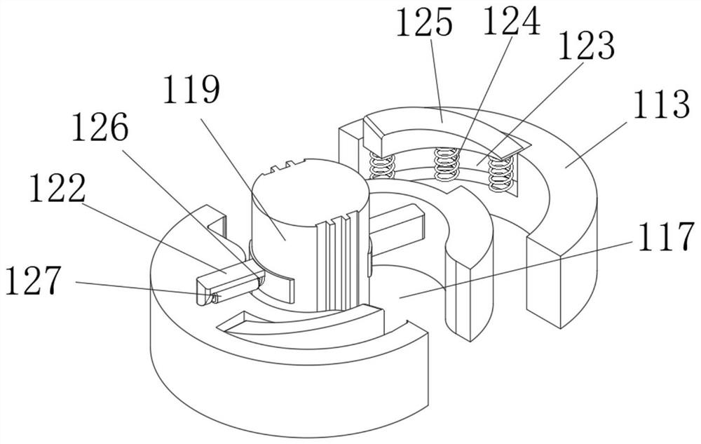
[0033] see Figure 1-8 , an embodiment provided by the present invention:

[0034] An annular welding device for a valve base used in valve production, comprising:

[0035] The device main body 1, the device main body 1 includes a main base plate 110, and one end of the main base plate 110 is fixedly installed with an auxiliary base plate 111;

[0036] The power box 112, the power box 112 is installed on the auxiliary base plate 111, the auxiliary base plate...


PUM


Abstract

The invention relates to the technical field of valve base welding, in particular to annular welding equipment of valve base for valve production. The annular welding equipment comprises a device main body, a power box and a control panel, wherein the device main body comprises a main bottom plate, and an auxiliary bottom plate is fixedly mounted at one end of the main bottom plate; the power box is installed on the auxiliary bottom plate, a telescopic sleeve is fixedly installed on the portion, on one side of the power box, of the auxiliary bottom plate, the power box communicates with the interior of the telescopic sleeve, and an extending opening is formed in one end of the telescopic sleeve; and the control panel is fixedly mounted on one surface of the power box. Through the arrangement of the extending opening, a lead screw, a threaded sleeve, a feeding barrel and a feeding groove, the feeding barrel and the feeding groove can ascend and descend through cooperation of the lead screw and the threaded sleeve, so that butt joint between a valve and the base is achieved, the situation that the feeding barrel blocks the valve on a clamping conveying belt to conduct alignment work is avoided, therefore, the working difficulty of workers is reduced, and continuous welding production is achieved.

Description

technical field [0001] The invention relates to the technical field of valve base welding, in particular to an annular welding equipment for valve bases used in valve production. Background technique [0002] Valves are pipeline accessories used to open and close pipelines, control flow direction, adjust and control the parameters (temperature, pressure and flow) of the conveying medium. According to its function, it can be divided into shut-off valve, check valve, regulating valve and so on. The valve is a control component in the fluid delivery system, which has functions such as cut-off, adjustment, flow diversion, reverse flow prevention, pressure stabilization, flow diversion or overflow pressure relief. Valves used in fluid control systems range from the simplest cut-off valves to various valves used in extremely complex automatic control systems, with a wide variety of varieties and specifications. Valves can be used to control the flow of various types of fluids su...

Claims


Application Information

Patent Timeline
Patent Type & Authority Applications(China)
IPC IPC(8): B23K37/00B23K37/02
CPCB23K37/0252B23K37/00
Inventor 段宏海
Owner 段宏海
Why Eureka
Try Eureka