Soluble bridge plug capable of being automatically released and using method thereof

A technology of soluble bridges and bridge plugs, which is applied in earth-moving drilling, wellbore/well components, sealing/packing, etc. The effect of reducing operating costs and reducing manufacturing costs

Inactive Publication Date: 2021-11-02
郭洪霞
View PDF0 Cites 0 Cited by
  • Summary
  • Abstract
  • Description
  • Claims
  • Application Information

AI Technical Summary

Problems solved by technology

[0003] In the prior art, the structure of the bridge plug and the supporting setting tool is complicated, and the working reliability needs to be improved

Method used


Image

  • Soluble bridge plug capable of being automatically released and using method thereof
  • Soluble bridge plug capable of being automatically released and using method thereof
  • Soluble bridge plug capable of being automatically released and using method thereof

Examples


Embodiment 1

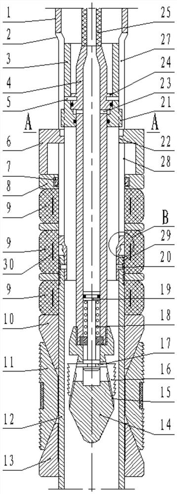
[0051] Such as figure 1 As shown, the present invention includes a bridge plug body and a setting tool. The structure of the bridge plug body includes a central tube, a rubber sleeve 9, slips 11, an upper cone 10 and a lower cone 13, and the rubber sleeve 9, the upper cone 10 and the lower cone. The cones 13 are all sleeved on the central tube, wherein the lower cone 13 is fixedly connected to the central tube, and the slips 11 are evenly arranged on the outer side of the central tube. The above are existing structures in the prior art, and will not be repeated here.

[0052] A major innovation of the present invention is that the setting tool is located inside the bridge plug body. The present invention creatively adopts the method of putting the setting tool into the tubing string to set the bridge plug. The high-pressure hose 25 greatly reduces the water consumption for setting. Only a small-displacement plunger pump is needed to complete the setting operation. There is n...

Embodiment 2

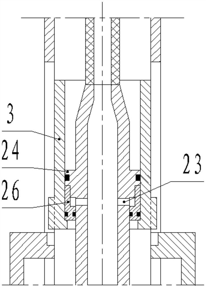
[0075] The difference between this embodiment and the first embodiment lies in the structure of the setting piston 3 .

[0076] Such as figure 2 As shown, as a preferred solution, the setting piston 3 is provided with an auxiliary piston 26, the auxiliary piston 26 is sleeved on the sliding tube 4 and is in sliding and sealing cooperation with the sliding tube 4, and the auxiliary piston 26 is located on the annular boss 24 Below, the outer diameter of the auxiliary piston 26 is equal to the outer diameter of the annular boss 24; the inner diameter of the lower end of the setting piston 3 is greater than the outer diameter of the guide head 14, so as to ensure that the guide head 14 passes through the setting piston 3 smoothly. At the same time, the inner diameter of the lower end of the setting piston 3 is smaller than the outer diameter of the auxiliary piston 26, so that the setting piston 3 can move downward under the push of the auxiliary piston 26.

[0077] Such as f...


PUM


Abstract

The invention relates to the technical field of downhole tools, in particular to a soluble bridge plug capable of being automatically released. The soluble bridge plug comprises a bridge plug body and a setting tool, wherein the bridge plug body structurally comprises a central tube, a rubber sleeve, slips, an upper cone and a lower cone, the rubber sleeve, the upper cone and the lower cone are all arranged on the central tube in a sleeving mode, the lower cone is fixedly connected onto the central tube, the slips are uniformly arranged on the outer side of the central tube, the setting tool is located inside the bridge plug body, the bridge plug body further a setting push sleeve, a clamp spring hanger and a C-shaped clamp spring, the setting push sleeve and the clamp spring hanger are all arranged on the central tube in a sleeving mode, the clamp spring hanger is positioned above the rubber sleeve, the setting push sleeve is positioned above the clamp spring hanger, an annular groove is processed on an inner side of the clamp spring hanger, and the C-shaped clamp spring is mounted in the annular groove. The soluble bridge plug uses a high-pressure-resistant hose with the very small diameter, so that the setting water consumption is greatly reduced; and setting can be completed only by arranging a small-displacement plunger pump during setting operation, a large water tank truck and a large pump truck do not need to be used, and therefore, the operation cost can be greatly reduced.

Description

technical field [0001] The invention belongs to the technical field of downhole tools, and in particular relates to a dissolvable bridge plug which can be automatically discarded and a use method thereof. Background technique [0002] The bridge plug is a downhole tool commonly used in oil fields. When in use, the bridge plug is lowered to a predetermined position in the downhole casing through the tubing string, and then the bridge plug is set by the corresponding setting method. After setting, the bridge plug passes through the The slips on it are anchored on the inner wall of the casing, and the casing is blocked by the rubber sleeve on it. [0003] In the prior art, the structure of the bridge plug and the supporting setting tool is complicated, and the working reliability needs to be improved. Therefore, it is necessary to design a new bridge plug to solve the problem. [0004] In addition, soluble bridge plugs are bridge plugs made of metal materials that are soluble...

Claims


Application Information

Patent Timeline
Patent Type & Authority Applications(China)
IPC IPC(8): E21B23/01E21B33/134
CPCE21B23/01E21B33/134
Inventor 郭洪霞
Owner 郭洪霞
Why Eureka
Try Eureka