Three-dimensional air-gap magnetic field testing device with double-layer rotating structure

A technology of air-gap magnetic field and rotating structure, which is applied in the direction of measuring devices, measuring magnetic variables, instruments, etc., can solve the problem that the three-dimensional transient air-gap magnetic field strength cannot be satisfied, the axial air-gap magnetic field strength of the motor cannot be measured, and the actual engineering cannot be satisfied. Questions such as requirements

Pending Publication Date: 2021-11-02
JIANGSU UNIV
View PDF1 Cites 0 Cited by
  • Summary
  • Abstract
  • Description
  • Claims
  • Application Information

AI Technical Summary

Problems solved by technology

However, it can only be used to measure the air-gap magnetic field strength generated by the relative motion of one rotor while the other rotor is fixed, and cannot measure the axial air-gap magnetic field strength of the motor because it cannot move axially, that is,

Method used


Image

  • Three-dimensional air-gap magnetic field testing device with double-layer rotating structure
  • Three-dimensional air-gap magnetic field testing device with double-layer rotating structure
  • Three-dimensional air-gap magnetic field testing device with double-layer rotating structure

Examples


Embodiment 1

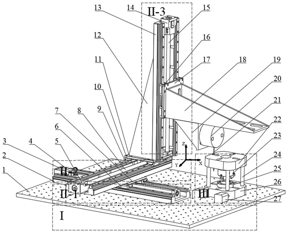
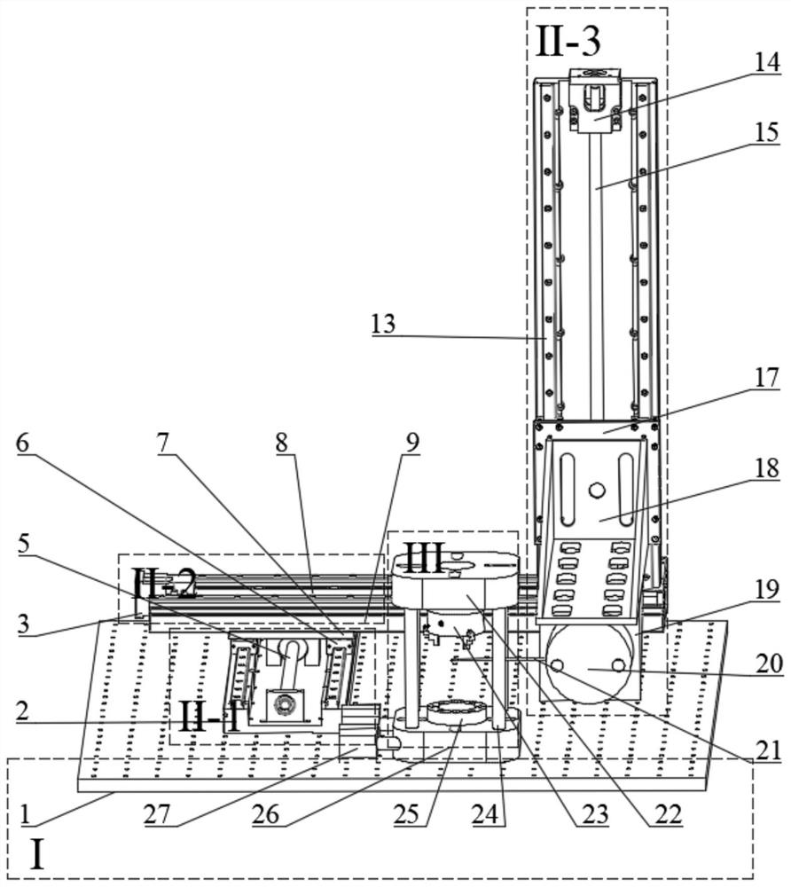
[0044] Such as Figure 6 As shown, when measuring the transient air-gap magnetic field strength of two disc rotors acting together, the rotating platform III needs to first extend the telescopic support column 24 to the longest, so as to facilitate the installation and fixation of the rotors. Fix the three-jaw chuck 23 on the upper turntable 25 through the through hole on the upper turntable 25 with screw connection, then fix the permanent magnet rotor 48 on the three-jaw chuck 23, the conductor rotor is installed on the lower turntable 25, and the rotor is installed After completion, adjust the distance between the two magnetic rotors to a suitable position by adjusting the telescopic support column 24, and then start the three driving motors on the displacement platform II to control the displacement platform II to move the three-dimensional Hall probe 21 to the horizontal State and located in the air gap between two flat disk magnetic rotors, such as Figure 8 (a) shown. ...

Embodiment 2

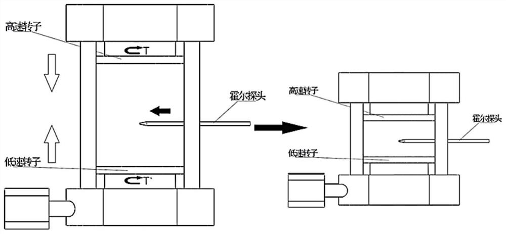
[0046] Such as Figure 7 Shown is the position and fixing method of the three-dimensional Hall probe 21 when measuring the transient air-gap magnetic field intensity of the joint action of two coaxial magnetic rotors. Such as Figure 9 Shown is a schematic diagram of the position of the three-dimensional Hall probe for measuring the air-gap magnetic field strength of the coaxial double magnetic rotor. The position of the three-dimensional Hall probe 21 is different depending on the measurement rotor. The three-dimensional Hall probe 21 position map when measuring the transient air gap magnetic field intensity generated by the coaxial magnetic gear, as shown in Figure 10 As shown in (a), when measuring the transient air-gap magnetic field strength of two coaxial rotors acting together, it is necessary to extend the telescopic support column 24 of the rotating platform III to the longest, so as to facilitate the installation and fixation of the rotors. Install the inner rotor...

Embodiment 3

[0048] When measuring the magnetic field intensity of the magnetic field modulation field generated when the outer rotor 51 and the magnetic field modulation device 52 work together, the flange of the magnetic field modulation device 52 needs to be removed first, and its structure is as follows: Figure 10 As shown in (b), the detachable magnetic modulation device 52 connects the flange and the main body of the magnetic modulation device 52 through threaded connection, and the main body of the magnetic modulation device 52 is made of nylon bar. The position and direction of the three-dimensional Hall probe 21 are as Figure 11 As shown in (b), the magnetic adjustment device 52 after the flange is removed is fixed on the three-jaw chuck 23 , and the outer rotor 51 is fixed on the lower turntable 25 . By adjusting the telescopic support column 24, the facing area of ​​the two rotors is the largest, that is, the active area of ​​the permanent magnet reaches the maximum value. Whe...


PUM


Abstract

The invention relates to a three-dimensional air-gap magnetic field testing device with a double-layer rotating structure, and mainly relates to a testing device and a measuring method for measuring a three-dimensional air-gap magnetic field. By controlling the upper-layer turntable rotating table and the lower-layer turntable rotating table which are of a double-layer structure to operate at different rotating speeds, the magnetic field intensity of a static air gap generated by a flat disc type or coaxial type magnetic gear and a single rotor of a magnetic coupler can be measured by applying a Hall sensor, and transient air-gap magnetic field intensity generated under the action of the two rotors and modulation magnetic field intensity generated by the rotors and the magnetic field adjusting device. By adopting the testing device and the testing method, the sizes of three-dimensional air gap magnetic fields in the radial direction, the circumferential direction and the axial direction of the inner rotor and the outer rotor of the magnetic gear and the magnetic coupler can be more conveniently measured, and the testing device and the testing method have certain experimental guiding significance on research on the transmission capacity of the magnetic gear and the coupler.

Description

technical field [0001] The invention relates to a three-dimensional air-gap magnetic field testing device with a double-layer rotating structure, and mainly relates to a testing device and a measuring method for measuring a three-dimensional air-gap magnetic field. It can operate at different speeds by controlling the upper and lower turntables of the double-layer structure, and use Hall sensors to measure the static air-gap magnetic field strength or two magnetic field strengths generated by a single rotor of a flat-disk or coaxial magnetic gear and a magnetic coupler. The transient air gap magnetic field intensity generated under the action of the rotor or the modulated magnetic field intensity generated by the combination of the magnetic rotor and the magnetic modulation device. Background technique [0002] Magnetic transmission is a transmission method that can realize synchronous or asynchronous motion through contactless connection. The size of the air gap magnetic f...

Claims


Application Information

Patent Timeline
IPC IPC(8): G01R33/07
CPCG01R33/07
Inventor 杨超君马帅张磊王凯高洋杨凡
Owner JIANGSU UNIV
Why Eureka
Try Eureka