

Aviation blade cross section molded line contour parameter evaluation method and system
An aviation blade and evaluation method technology, applied in character and pattern recognition, special data processing applications, instruments, etc., can solve the problems of torsion angle and offset evaluation, complex calculation, and numerous parameters, and achieve accurate and reliable evaluation
- Summary
- Abstract
- Description
- Claims
- Application Information
AI Technical Summary
Problems solved by technology
Method used
Image

Examples
Embodiment Construction
[0052] In order to make the object, technical solution and advantages of the present invention clearer, the present invention will be further described in detail below in conjunction with the accompanying drawings and embodiments. It should be understood that the specific embodiments described here are only used to explain the present invention, not to limit the present invention. In addition, the technical features involved in the various embodiments of the present invention described below can be combined with each other as long as they do not constitute a conflict with each other.
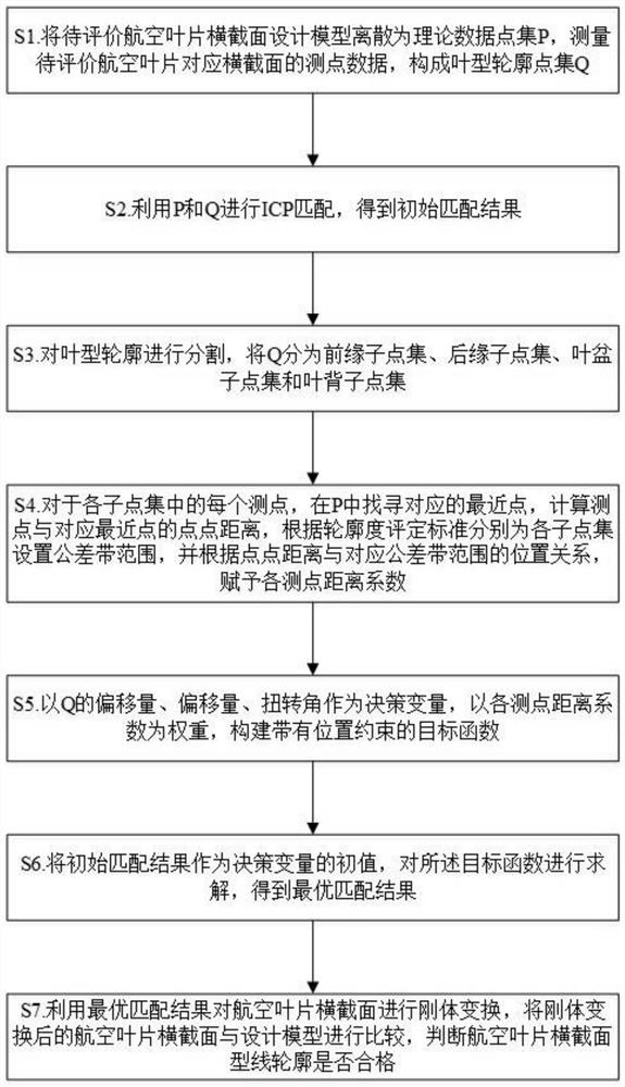
[0053] Such as figure 1 As shown, the present invention provides a method for evaluating the profile parameters of the cross-section of an aviation blade, comprising the following steps:
[0054] (1) Use the three-coordinate measuring machine method in the contact measurement to obtain the measuring point data of each section of the blade to form the blade profile point set Q;
[0055] (2) Use...
PUM
 Abstract
Description
Claims
Application Information