A support frame for an electromechanical engineering control cabinet

A control cabinet and support frame technology, which is applied to electrical components, substation/switch layout details, substation/distribution device enclosures, etc., can solve the problems of large occupied area, many fixing mechanisms, and increased volume and weight of the control cabinet. Small occupied area, reasonable installation structure and space saving effect

Active Publication Date: 2021-12-07
深圳市飞霞机电技术有限公司
View PDF1 Cites 0 Cited by
  • Summary
  • Abstract
  • Description
  • Claims
  • Application Information

AI Technical Summary

Problems solved by technology

[0002] The control cabinet is to assemble the switchgear, measuring instrument, protective device and auxiliary equipment in the closed or semiclosed metal cabinet or on the screen width according to the requirements of electrical wiring. The main function of the control cabinet is to set various switches, relays or PLC logic editors inside. Due to the large load demand in the electromechanical engineering of the existing control cabinet, the volume and weight of the control cabinet increase. , which in turn makes it inconvenient to install and stabilize, affecting its normal use
[0003] In order to solve the above problems, the Chinese patent application number CN201910938721.X provides a support frame for electromechanical engineering control cabinets, including a concave carrier, in which a side clamping mechanism, a bottom clamping mechanism and a top fixing Mechanism; the concave carrier includes a built-in cavity; both sides in the cavity are vertically provided with a first transmission shaft, the top of the first transmission shaft extends to the top of the concave carrier, and the bottom of the first transmission shaft Extending to the bottom of the cavity, although this patent can fix the control cabinet, the components used to control the action of the fixing mechanism are the motor and the multiple transmission shafts that drive each fixing mechanism to fix the control cabinet through the motor. The fixing mechanism involved More, occupy a larger area after installation

Method used


Image

  • A support frame for an electromechanical engineering control cabinet
  • A support frame for an electromechanical engineering control cabinet
  • A support frame for an electromechanical engineering control cabinet

Examples


Embodiment Construction

[0022] The following is a clear and complete description of the technical solution of the patent of the present invention in conjunction with the accompanying drawings. Apparently, the described embodiments are part of the embodiments of the present invention, not all of them. Based on the embodiments of the present invention, all other embodiments obtained by those skilled in the art without creative efforts fall within the protection scope of the present invention.

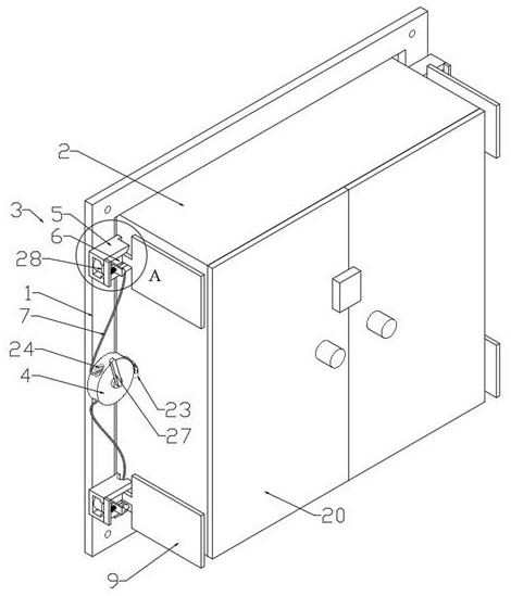
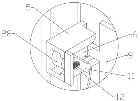
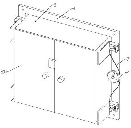
[0023] like Figure 1 to Figure 8 As shown, this embodiment provides a support frame for an electromechanical engineering control cabinet, which includes a frame 1 and a control cabinet 2 installed on a building through the frame 1. A locking mechanism 3 is provided on the frame 1, and the locking mechanism 3 is Four, two groups of two and two sets of locking mechanisms 3 are located on both sides of the control cabinet 2, and the upper and lower locking mechanisms 3 on the same side are provided with a guide pl...


PUM


Abstract

The invention provides a support frame for an electromechanical engineering control cabinet, which relates to the technical field of control cabinet installation. The support frame for an electromechanical engineering control cabinet includes a frame and a control cabinet installed on a building through the frame. The frame is provided with a locking mechanism. On both sides of the cabinet, between the upper and lower locking mechanisms on the same side, there is a guide seat plate fixed on the front wall of the frame, the two sides of the control cabinet are provided with perforations corresponding to the inside and outside of the guide seat plate, and the guide seat plate is provided with There are two upper and lower guide holes. The locking mechanism includes a guide frame with slide rails and a limit frame that slides into the guide frame through the slide rails. The locking mechanism on this fixing device has a more reasonable installation structure and is only installed on both sides of the frame. , occupies a small area.

Description

technical field [0001] The invention relates to the technical field of control cabinet installation, in particular to a support frame for an electromechanical engineering control cabinet. Background technique [0002] The control cabinet is to assemble the switchgear, measuring instrument, protective device and auxiliary equipment in the closed or semiclosed metal cabinet or on the screen width according to the requirements of electrical wiring. The main function of the control cabinet is to set various switches, relays or PLC logic editors inside. Due to the large load demand in the electromechanical engineering of the existing control cabinet, the volume and weight of the control cabinet increase. , which in turn makes it inconvenient to install and stabilize, affecting its normal use. [0003] In order to solve the above problems, the Chinese patent application number CN201910938721.X provides a support frame for electromechanical engineering control cabinets, including ...

Claims


Application Information

Patent Timeline
Patent Type & Authority Patents(China)
IPC IPC(8): H02B1/42H02B1/30
Inventor 颜俊伟
Owner 深圳市飞霞机电技术有限公司
Why Eureka
Try Eureka