
A spliced ​​dust-proof and explosion-proof electrical component

An explosion-proof, splicing technology, which is applied in the direction of electrical components, electrical equipment structural parts, casing/cabinet/drawer parts, etc. Avoid problems such as shielding, to save trouble in use, simplify the operation process of disconnecting wires, and ensure the effect of heat dissipation

Active Publication Date: 2021-11-30
江苏西欧电子有限公司
View PDF4 Cites 0 Cited by
  • Summary
  • Abstract
  • Description
  • Claims
  • Application Information

AI Technical Summary

Problems solved by technology

[0005] The purpose of the present invention is to provide a spliced ​​dust-proof and explosion-proof electrical component to solve the problem in the above-mentioned background technology that the setting position of the heat-dissipating and air-permeable filter is not reasonable enough, and most of them are exposed directly to the wind, lack of shelter, and are easy to accumulate dust.

Method used

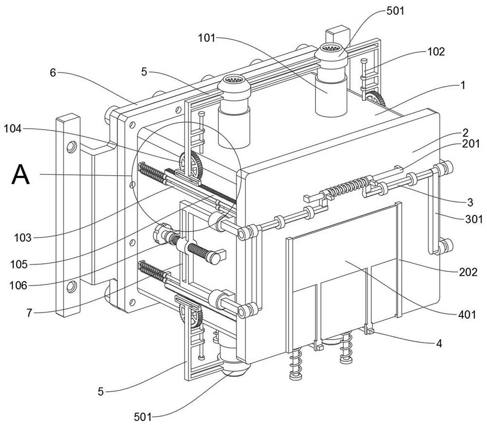

Image

  • A spliced ​​dust-proof and explosion-proof electrical component
  • A spliced ​​dust-proof and explosion-proof electrical component
  • A spliced ​​dust-proof and explosion-proof electrical component

Examples


Embodiment 1

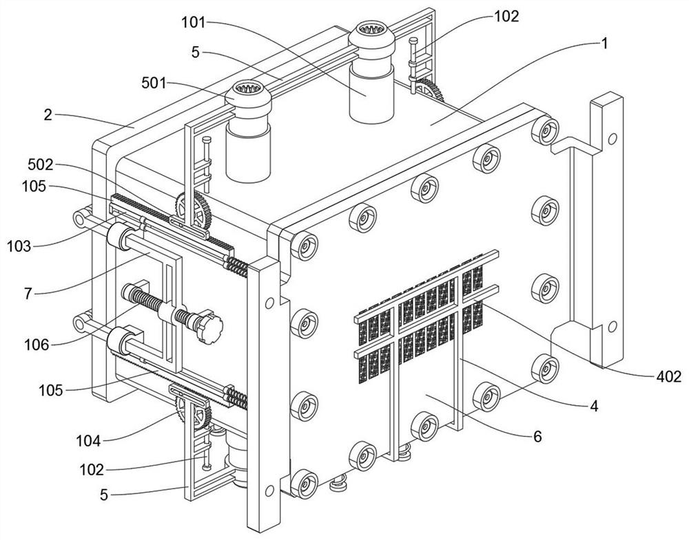
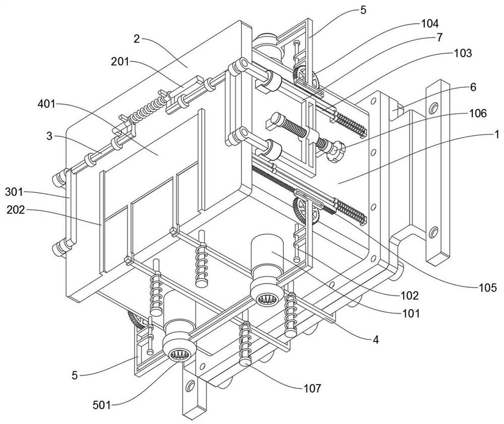
[0025] see Figure 1 to Figure 9 , Embodiment 1 provided by the present invention: a spliced ​​dust-proof and explosion-proof electrical component, including an electric box shell 1; the electric box shell 1 includes a vertical support positioning shaft 102, a suspension shaft 107, and the electric box shell 1 has a square structure as a whole. There is a rectangular cover plate 2 on the sliding cover on the front opening, a square rear end cover 6 on the rear locking cover, and four vertical braces are welded and fixed symmetrically in the middle, left and right sides of the upper and lower side plates of the electric box shell 1. Positioning shaft 102, the four vertical support positioning shafts 102 are slidingly fitted with two force transmission frames 5, and four hanging shafts 107 are symmetrically welded on the lower side plate of the electric box shell 1, and the four hanging shafts 107 are pushed and slid by springs There are two synchronous frames 4 in the suit; the...

Embodiment 2

[0032] Please refer to 10, the second embodiment provided by the present invention: a spliced ​​dust-proof and explosion-proof electrical assembly, including, the rear end cover 6 includes a flat mounting plate 601, and the left and right sides of the rear end cover 6 are supported by two L-shaped supports The board is welded with two mounting strips with holes, and the inner end surface of the rear end cover 6 is welded and supported with a thick-shaped installation plate 601, and a row of cooling grooves is opened in the middle of the rear end cover 6. In this row of cooling grooves There is a row of nylon filter screens embedded in it, and the space supported by the two L-shaped support plates on the left and right sides of the rear end cover 6 can facilitate the air flow of the heat sink, ensuring the heat dissipation performance of the electric box shell 1, and a row of heat sinks is hidden in the The relatively concealed installation between the wall and the rear end cove...


PUM


Abstract

The invention discloses a spliced ​​dust-proof and explosion-proof electrical component, which relates to the technical field of explosion-proof electrical equipment, and solves the problem that the existing electrical components have unreasonable installation positions of heat-dissipating and ventilating filters, and most of them are directly exposed to the wind, lacking shielding, and easy to accumulate dust. A spliced ​​dust-proof and explosion-proof electrical component includes an electric box shell; the electric box shell has a square structure as a whole, and a rectangular cover plate is provided on the front opening for sliding and plugging, and the rear end is locked and sealed with a square back cover. The end cover, and the middle, left and right sides of the upper and lower side plates of the electric box shell are symmetrically welded and fixed with four vertical support positioning shafts. There are two force transmission frames on the four vertical support positioning shafts. The lower side plate of the electric box shell Symmetrically welded with four hanging shafts. The invention uses two synchronization frames to pull down the steel cover to view the screen data, and can drive the two horizontal support brush rods to slide together to brush and clean the nylon filter screen, which saves the trouble of manually cleaning the filter screen on a regular basis.

Description

technical field [0001] The invention relates to the technical field of explosion-proof electrical appliances, in particular to a spliced ​​dust-proof and explosion-proof electrical component. Background technique [0002] In public places with a large number of people, such as stations and certain halls and meeting rooms in parks, in order to ensure the safety of personnel and avoid short-circuit self-explosion of electrical components, explosion-proof electrical appliances are generally selected when selecting electrical appliances. [0003] For example, patent No. CN201910021236.6 discloses an outdoor retractable photovoltaic distribution box, including a distribution box, a fixing seat is provided on the top of the distribution box, and a photovoltaic An integrated device, the inside of the distribution box is provided with a cable partition, the surface of the cable partition is provided with a cable hole, and the inside of the distribution box is located above the cable...

Claims


Application Information

Patent Timeline
Patent Type & Authority Patents(China)
IPC IPC(8): H05K5/02H05K7/20
CPCH05K5/0217H05K5/0213H05K5/0247H05K5/0204H05K7/20127H05K5/03
Inventor 张裕宾
Owner 江苏西欧电子有限公司
Learn More