
Process for forming sharp corner at rotating shaft of notebook shell

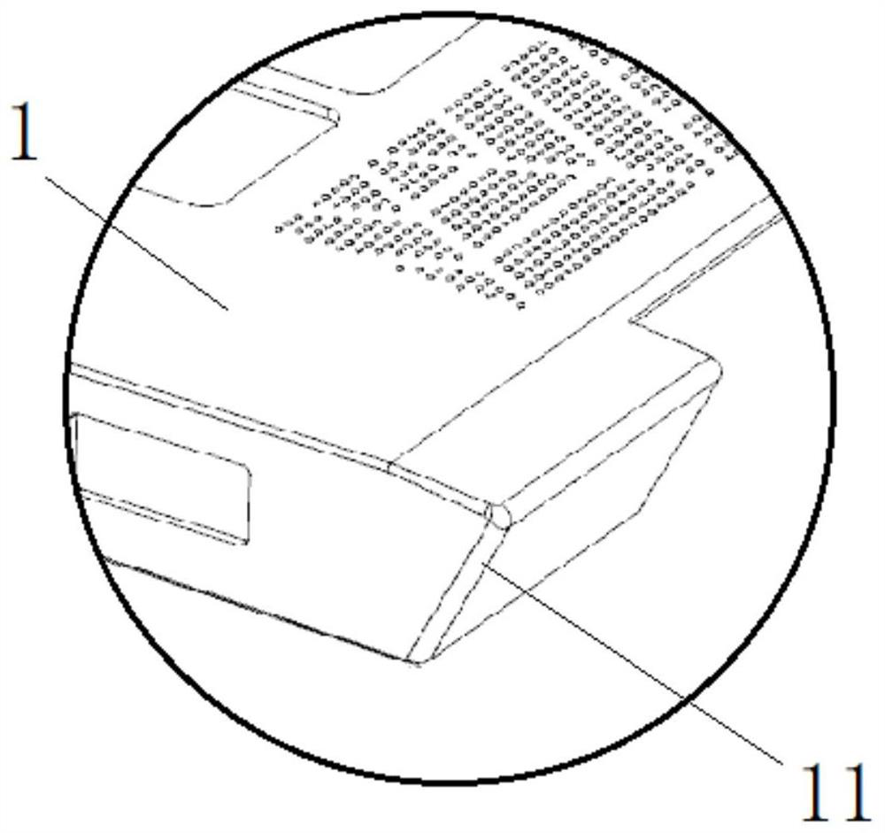
A notebook shell and forming process technology, applied in the field of metal stamping processing, can solve problems such as unrealizable, easy to collapse, sharp corners 11 easy to crack, etc., to achieve the effect of meeting structural requirements and avoiding cracking

Active Publication Date: 2021-11-05
SUZHOU CHUNQIU ELECTRONICS TECH
View PDF9 Cites 0 Cited by
  • Summary
  • Abstract
  • Description
  • Claims
  • Application Information

AI Technical Summary

Problems solved by technology

[0004] 1. Because of the large deformation of the material, the sharp corner 11 is easy to crack;
[0005] 2. The height of the rotating shaft cannot meet the product requirements;
[0006] 3. The front R0.8 angle is easy to collapse, which cannot be realized

Method used


Image

  • Process for forming sharp corner at rotating shaft of notebook shell
  • Process for forming sharp corner at rotating shaft of notebook shell
  • Process for forming sharp corner at rotating shaft of notebook shell

Examples


Embodiment

[0037] Such as Figure 1 to Figure 6 As shown in the present invention, a sharp corner forming process at the rotating shaft of a notebook casing, the steps include:

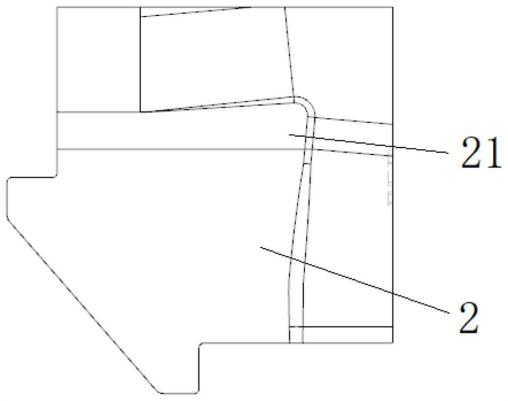
[0038] ① Make a 75-80° horn angle on the edge of the flat material, the bending angle of the two side walls is 50-52°, and the sharp corner protrudes 0.28-0.30mm. Here, the horn angle of the edge of the material is obtained by punching the first horn part 21 on the first corner forming block 2. This structure allows the material at the sharp corner to be pulled out more, leaving room for the sharp corner deformed into a corner later. Enough material so as not to pull off.

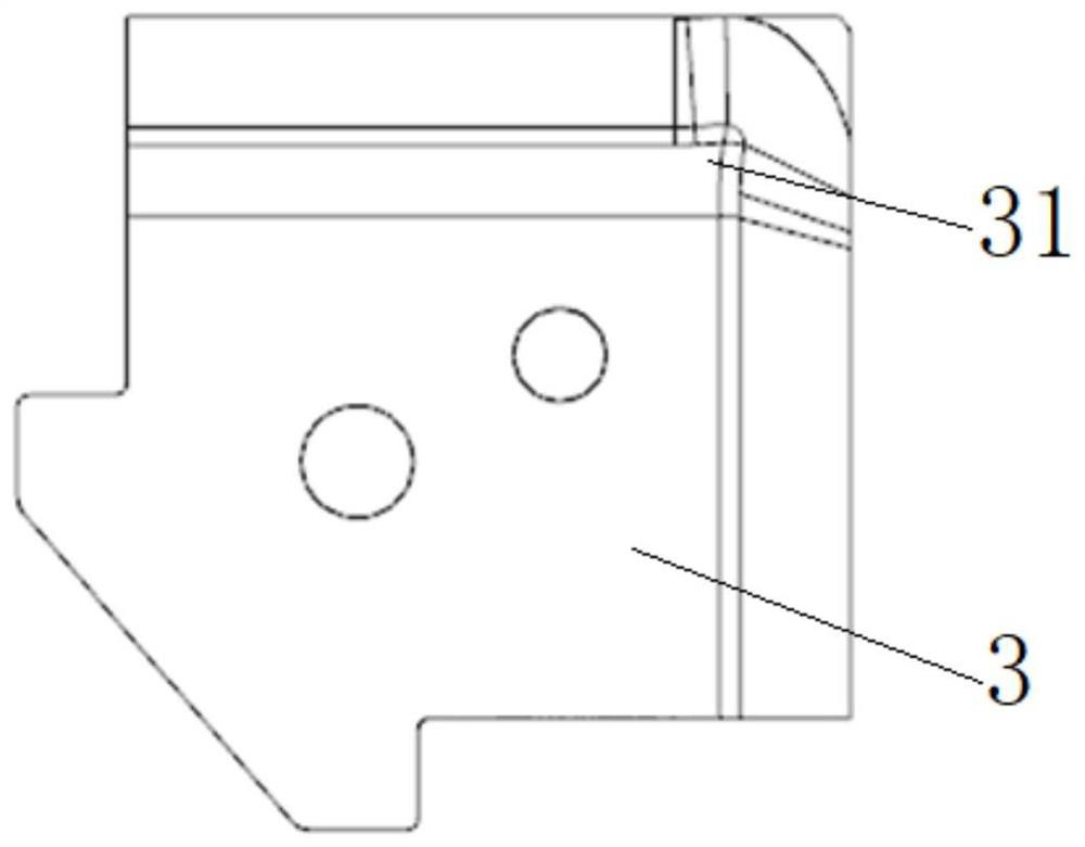
[0039] ② Make an angle of 83-85° on the edge of the material, the bending angle of the two side walls is 70-72°, and the sharp corner protrudes 0.20-0.22mm. Here the bending angle is further enlarged, and the corner angle of the material edge is obtained by stamping the second corner part 31 on the second corner forming block 3 , this struc...


PUM


Abstract

The invention belongs to the technical field of metal stamping machining, and relates to a process for forming a sharp corner at a rotating shaft of a notebook computer shell. The process comprises the steps of carrying out 50-52-degree ox horn bending, carrying out 70-72-degree ox horn bending, carrying out 90-degree right-angle bending, carrying out 100-degree bending and carrying out 110-degree bending. According to the process, a material of a flat plate structure can be transformed into a sharp-corner-shaped rotating shaft structure with two side walls through five-step deformation, so that not only is the structural requirement met, but also cracking can be avoided.

Description

technical field [0001] The invention relates to the technical field of metal stamping processing, in particular to a sharp corner forming process at the rotating shaft of a notebook casing. Background technique [0002] With the competitive development of my country's mold industry, the mold consumption of my country's general technical level has been relatively saturated, and there is still a large market space for the demand for mold products with high technical content, which determines that my country's mold industry has any demand for high-end Make great improvements to break through the current technical bottlenecks. In recent years, 3C product molds based on notebook computers are represented. In order to match the existing 5G technology and people's aesthetics, the products not only improve in performance but also make breakthroughs in appearance. Enterprises are facing a period of transition, and it is necessary to introduce new technologies to continuously break th...

Claims


Application Information

Patent Timeline
IPC IPC(8): B21D19/00B21D11/18
CPCB21D19/00B21D11/18
Inventor 孙华军
Owner SUZHOU CHUNQIU ELECTRONICS TECH
Learn More