Foaming agent uncoupled explosive loading blasting method

A foaming agent and charging technology, applied in the field of rock blasting, can solve the problems of low construction efficiency and low positioning accuracy in holes, and achieve the effects of low cost, good on-site operability and high compressibility

Inactive Publication Date: 2018-06-29
XINJIANG UNIVERSITY
View PDF1 Cites 0 Cited by
  • Summary
  • Abstract
  • Description
  • Claims
  • Application Information

AI Technical Summary

Problems solved by technology

[0005] In view of the problems of low positioning accuracy and low construction efficiency in the actual construction of uncoupled charge, the invention provides a high-efficiency and low-cost charge method based on foaming agent materials

Method used


Image

  • Foaming agent uncoupled explosive loading blasting method
  • Foaming agent uncoupled explosive loading blasting method

Examples


Embodiment Construction

[0023] Preferred embodiments of the present invention will be described in detail below in conjunction with the accompanying drawings, so that the advantages and features of the present invention can be more easily understood by those skilled in the art, but the embodiments of the present invention are not limited thereto.

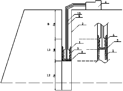
[0024] Optimum embodiment: the blasting method of the present invention is explained by taking a sectioned radial uncoupled blast hole in an open-pit mine as an example, which is specifically described below in conjunction with the accompanying drawings:

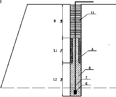
[0025] like figure 1 As shown, according to the actual formation conditions, the blast hole is designed as a segmented charge structure, the blast hole diameter is 138mm, the step height is 10m, the super depth is 1m, the filling section D=4m, the upper section is uncoupled charge length L1=3m, and the lower section is coupled The charge length is L2=4m.

[0026] (1) First, according to the uncoupling c...


PUM


Abstract

The invention aims to solve the problems of time-consuming and labor-consuming cartridge manufacturing process and low in-hole positioning precision in an uncoupled explosive loading blasting process,discloses a foaming agent uncoupled explosive loading blasting method, and relates to the technical field of rock-mass blasting. Foaming agents are sprayed to the inner wall of a blast hole to changethe inner diameter of the blast hole. One or more annular foam structure is directly formed in the hole, the manufacturing link of a grain is omitted, and radial and axial positioning precision of explosives is improved. The foaming agents serve as structure forming materials, the method has the advantages of forming rapidness and low cost, a radial space still has high compressibility, and the requirement of uncoupled explosive loading blasting for principles is met. The process is simple, on-site operability is good, various loading structures can be formed, and adaptability is strong.

Description

technical field [0001] The invention relates to the technical field of rock mass blasting, in particular to a foaming agent uncoupled charge blasting method. Background technique [0002] The charge structure in the blast hole can generally be divided into two types: coupled and uncoupled according to whether the explosive is in contact with the hole wall or not. The uncoupled charge structure acts on the detonation wave through the air layer between the charge column and the hole wall during the explosion. Cracks are generated in the rocks of the surrounding hole walls, and at the same time, the air layer is compressed to store part of the energy in time, avoiding the excessive crushing of the rocks, and in the subsequent process, the compressed air layer releases this energy to the crack area, increasing the crack area In the whole process of blasting, the energy is reasonably and evenly utilized, which reduces the consumption of explosives and blasting equipment and reduc...

Claims


Application Information

Patent Timeline
Patent Type & Authority Applications(China)
IPC IPC(8): F42D1/08F42D3/04
CPCF42D1/08F42D3/04
Inventor 管伟明陈辉刘青松温颖远张华栋史维生
Owner XINJIANG UNIVERSITY
Why Eureka
Try Eureka