Array type magnetic path and array type magnetic path motor sound transducer

An array type and transducer technology, applied in the direction of sensors, electrical components, etc., can solve problems such as difficult to adapt to energy-consuming electronic equipment, achieve flexible and diverse magnetic field orientation, simple magnetic circuit structure, and improve energy conversion efficiency.

Inactive Publication Date: 2012-07-04
王兴荣
View PDF1 Cites 0 Cited by
  • Summary
  • Abstract
  • Description
  • Claims
  • Application Information

AI Technical Summary

Problems solved by technology

However, it is also limited by its magnetic circuit structure, and it is difficult to meet the needs of electronic equipment with low energy consumption and special shape requirements.

Method used


Image

  • Array type magnetic path and array type magnetic path motor sound transducer
  • Array type magnetic path and array type magnetic path motor sound transducer
  • Array type magnetic path and array type magnetic path motor sound transducer

Examples


Embodiment Construction

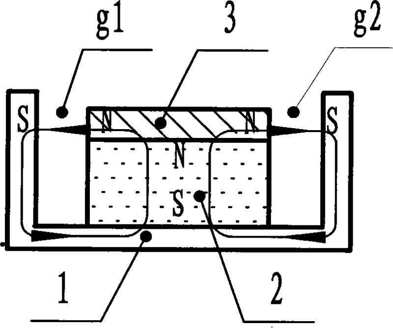
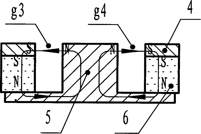
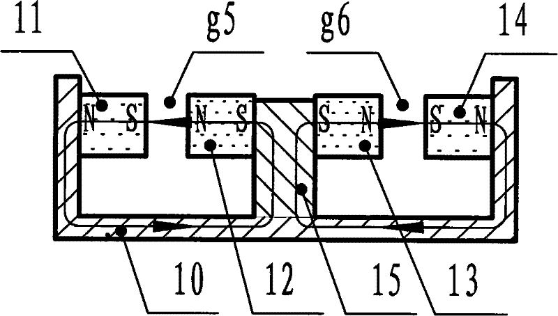
[0051] image 3 It is a schematic diagram of the magnetic circuit formed by the array magnetic circuit of the present invention, image 3 Among them, a magnetically conductive plate 15 is provided in the magnetically permeable bracket 10, magnets 12 and magnets 13 are provided on both sides of the magnetically permeable plate 15, and magnets 11 and 13 are respectively correspondingly provided on the magnetically permeable bracket 10. Magnet 14 forms two magnetic field forming parts, namely, the magnet pair in the left magnetic field forming part in the figure is magnet 11 and magnet 12, and there is a magnetic gap g5 between magnet 11 and magnet 12. Similarly, the magnet pair in the right magnetic field forming part is The magnet 13 and the magnet 14 have a magnetic gap g6 between the magnet 13 and the magnet 14 .

[0052] The polarity direction of magnet 11 and magnet 12 in the left side forming part is the same, the polarity direction of magnet 13 and magnet 14 in the right...


PUM


Abstract

The invention discloses an array-type magnetic circuit. A plurality of groups of magnets are arranged in a conventional magnetic conductive support to form a magnetic field forming part in a manner of various combinations; magnetic clearances used for putting coils are reserved among the magnets; the magnetic circuit has the common characters that the polarities of the magnets on both sides of the same magnetic clearance are arranged in the same direction, and opposite to the polarities of the magnets on both sides of the other magnetic clearance, so as to ensure that driving forces of magnetic force lines generated by a plurality of groups of magnets to the coils in the magnetic clearances are superposed in the same direction. The invention further discloses a transducer of an array-typemagnetic circuit made by adopting the magnetic circuit; a coil and a vibrating membrane in the transducer can be connected in a parallel manner or a perpendicular manner, and is matched with the magnetic circuit. The magnetic circuit and the transducer have the advantages of low energy consumption, high efficiency, small distortion and compact structure; furthermore, the magnetic circuit and the transducer can be made into various shapes that are particularly suitable for long-narrow or gap-shaped structures, and include various fields such as communication and, broadcast fields.

Description

technical field [0001] The invention relates to the design of miniature, long and narrow and special-shaped electric magnetic circuit and the electromechanical sound transducer prepared by using the magnetic circuit. Background technique [0002] There are two types of traditional miniature electric magnetic circuits: internal magnetic circuit and external magnetic circuit. Internal magnetic circuit such as figure 1 As shown, the magnetic field lines emitted by the N pole of the cylindrical magnet 2 pass through the magnetic plate (pole chip) 3 close to the N pole of the cylindrical magnet 2, pass through the magnetic gap g1 and the magnetic gap g2, and reach the magnetic conductive bowl 1 Returning to the S pole of the magnet 2, a complete magnetic circuit is formed. [0003] External magnetic circuit such as figure 2 As shown, the magnetic field lines emitted by the N pole of the ring magnet 6 pass through the field core 5 of the T iron, pass through the magnetic gap g...

Claims


Application Information

Patent Timeline
Patent Type & Authority Patents(China)
IPC IPC(8): H04R9/02H04R9/06
Inventor 王兴荣
Owner 王兴荣
Why Eureka
Try Eureka