
Pile foundation quality detection system

A detection system and pile foundation technology, which is applied in the fields of infrastructure engineering, infrastructure testing, construction, etc., can solve problems such as detection errors and sound wave changes, and achieve the effects of eliminating interference, driving stability, and ensuring accuracy

Active Publication Date: 2021-11-05
EASTERN GANSU UNIVERSITY
View PDF7 Cites 2 Cited by
  • Summary
  • Abstract
  • Description
  • Claims
  • Application Information

AI Technical Summary

Problems solved by technology

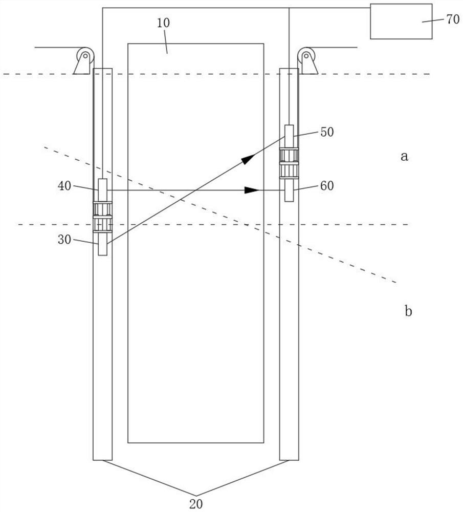
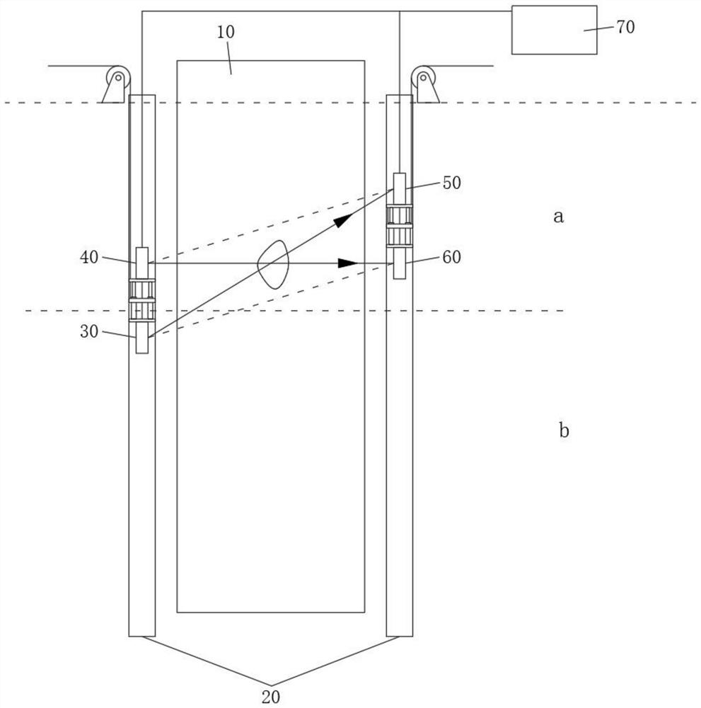
However, in the actual application of this method, there will be a certain distance between the acoustic measuring tube and the concrete pile foundation, so the sound wave can only reach the sensor after passing through the soil around the pile and the concrete pile foundation. Based on this, when the impedance difference in the soil around the pile is large Large uneven layers (such as soft clay layer and hard rock layer) will also cause changes in sound waves, which will lead to detection errors

Method used


Image

  • Pile foundation quality detection system
  • Pile foundation quality detection system
  • Pile foundation quality detection system

Examples


Embodiment 1

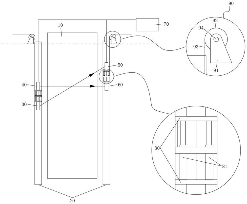
[0030] see figure 1 As shown, a kind of pile foundation quality detection system is provided in the present invention, and this detection system mainly comprises:

[0031] Pile foundation 10 to be tested;

[0032] Two acoustic tubes 20;

[0033] The first ultrasonic probe 30 and the second ultrasonic probe 40;

[0034] a first ultrasonic sensor 50 and a second ultrasonic sensor 60;

[0035] Decentralization assembly 90;

[0036] Data Analyzer 70.

[0037] the above

[0038] About the acoustic measuring tube 20: two acoustic measuring tubes 20 are arranged in the pile surrounding soil of the pile foundation 10 to be detected, and the two acoustic measuring tubes 20 are symmetrically distributed on both sides of the pile foundation 10 to be detected;

[0039] specific:

[0040] The acoustic tube 20 is a PVC tube, and each acoustic tube 20 is a structure with a closed bottom and an open top;

[0041] The acoustic tube 20 is parallel to the pile foundation 10 to be detecte...

Embodiment 2

[0055] see figure 1 As shown, a kind of pile foundation quality detection system is provided in the present invention, and this detection system mainly comprises:

[0056] Pile foundation 10 to be tested;

[0057] Two acoustic tubes 20;

[0058] The first ultrasonic probe 30 and the second ultrasonic probe 40;

[0059] a first ultrasonic sensor 50 and a second ultrasonic sensor 60;

[0060] Decentralization assembly 90;

[0061] the first distance adjuster and the second distance adjuster;

[0062] Data Analyzer 70.

[0063] It can be seen from the above that the difference between this embodiment and the first embodiment is that the first distance adjuster and the second distance adjuster are added; specifically, the first distance adjuster and the second distance adjuster realize synchronous and reverse distance adjustment, and the second distance adjuster A distance adjuster is arranged between the first ultrasonic probe 30 and the second ultrasonic probe 40, and the ...


PUM


Abstract

The invention belongs to the technical field of pile foundation quality detection, and discloses a pile foundation quality detection system. The pile foundation quality detection system comprises a to-be-detected pile foundation, two sounding pipes, a first ultrasonic probe, a second ultrasonic probe, a first ultrasonic wave sensor, a second ultrasonic wave sensor, and lowering assemblies; the two sounding pipes are symmetrically distributed on the two sides of the to-be-detected pile foundation; the first ultrasonic probe and the second ultrasonic probe are arranged in one of the sounding pipes; the first ultrasonic probe is located below the second ultrasonic probe; the first ultrasonic wave sensor and the second ultrasonic wave sensor are arranged in the other sounding pipe; the second ultrasonic wave sensor is located below the first ultrasonic wave sensor; the first ultrasonic wave sensor detects first-frequency ultrasonic waves emitted by the first ultrasonic probe; the second ultrasonic wave sensor detects second-frequency ultrasonic waves emitted by the second ultrasonic probe; the two lowering assemblies respectively correspond to the two sounding pipes; and the two lowering assemblies synchronously realize equidistant lowering of the first ultrasonic probe and the second ultrasonic probe as well as the first ultrasonic wave sensor and the second ultrasonic wave sensor in the two sounding pipes.

Description

technical field [0001] The invention belongs to the technical field of pile foundation quality detection, and in particular relates to a pile foundation quality detection system. Background technique [0002] The pile foundation is a force-transmitting member with a certain rigidity and strength that transfers the superstructure load into the rock foundation. Therefore, the quality of the pile foundation itself is an important factor to ensure the safety of the entire engineering structure. At present, there are many pile foundation detection methods in our country, including drilling coring method, acoustic transmission method, high strain method and low strain method, etc. [0003] The sound wave transmission method refers to the method of transmitting and receiving sound waves between the embedded acoustic measuring tubes, and detecting the integrity of the pile body by measuring the relative changes of acoustic parameters such as sound time, frequency and amplitude atten...

Claims


Application Information

Patent Timeline
Patent Type & Authority Applications(China)
IPC IPC(8): E02D33/00
CPCE02D33/00
Inventor 张兴元闫铁成
Owner EASTERN GANSU UNIVERSITY
Learn More