Self-dredging anti-blocking water pump
An anti-clogging and water pump technology, applied in the direction of pumps, pump devices, pump components, etc., can solve the problems of easy-to-block pipes of water pumps, overload damage of water pump drive devices, lack of anti-clogging, etc., to achieve reasonable structure, improve fluency, clear effect
- Summary
- Abstract
- Description
- Claims
- Application Information
AI Technical Summary
Problems solved by technology
Method used
Image
Examples
Embodiment 1
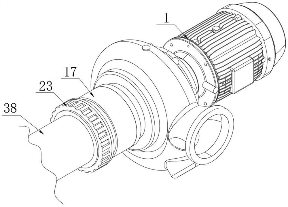
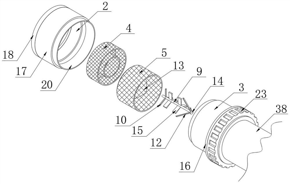
[0031] Refer to attached Figure 1-6 , a self-dredging anti-clogging water pump provided by the present invention includes a water pump body 1, one end of the water pump body 1 is fixedly connected with a water inlet pipe 2, and an anti-blocking connection mechanism is provided at the end of the water inlet pipe 2 far away from the water pump body 1;
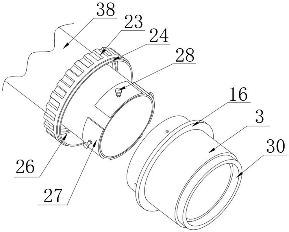
[0032] The anti-blocking connection mechanism includes a connecting pipe 3, a first collecting net 4 and a second collecting net 5, the connecting pipe 3 is located at the end of the water inlet pipe 2 away from the water pump body 1, and the water pump body 1 is fixedly connected with a motor 6 The output end of the motor 6 is fixedly connected with a rotating bar 7, and the surface of the end of the rotating bar 7 away from the motor 6 is provided with a threaded hole, and the first collecting net 4 and the second collecting net 5 are respectively located inside the connecting pipe 3 On both sides, a fixed retaining ring 8 is pr...
Embodiment 2
[0044] Refer to attached Figure 7 , a self-draining anti-clogging water pump provided by the present invention, the sealing and clamping assembly includes a sealing ring sleeve 17, the sealing ring sleeve 17 is located outside the end of the connecting pipe 3 close to the water inlet pipe 2, and the inside of the sealing ring sleeve 17 is The two ends are respectively threadedly connected with the connection pipe 3 and the water inlet pipe 2, and one end of the sealing ring sleeve 17 is provided with a limit stop ring 18, and the limit stop ring 18 is fixedly connected with the water inlet pipe 2, and the seal ring sleeve 17 An annular chute 19 is provided on the inner surface of the end away from the limit stop ring 18, and an annular clamp 20 is fixedly connected to one side of the fixed ring 16, and the end of the annular clamp 20 away from the fixed ring 16 slides with the annular chute 19 connected, the sealing annular sleeve 17 is provided with a first arc groove 31 on ...
PUM
 Abstract
Description
Claims
Application Information
 - R&D
- Intellectual Property
- Life Sciences
- Materials
- Tech Scout
- Unparalleled Data Quality
- Higher Quality Content
- 60% Fewer Hallucinations
Browse by: Latest US Patents, China's latest patents, Technical Efficacy Thesaurus, Application Domain, Technology Topic, Popular Technical Reports.
© 2025 PatSnap. All rights reserved.Legal|Privacy policy|Modern Slavery Act Transparency Statement|Sitemap|About US| Contact US: help@patsnap.com


