Marine radar information fusion-based marine target joint detection method
A marine radar and joint detection technology, applied in the direction of measurement device, use of re-radiation, radio wave measurement system, etc., can solve problems such as blind spot situation cannot be observed, target cannot be effectively tracked, etc., to achieve the effect of ensuring navigation safety
- Summary
- Abstract
- Description
- Claims
- Application Information
AI Technical Summary
Problems solved by technology
Method used
Image

Examples
specific Embodiment approach 1
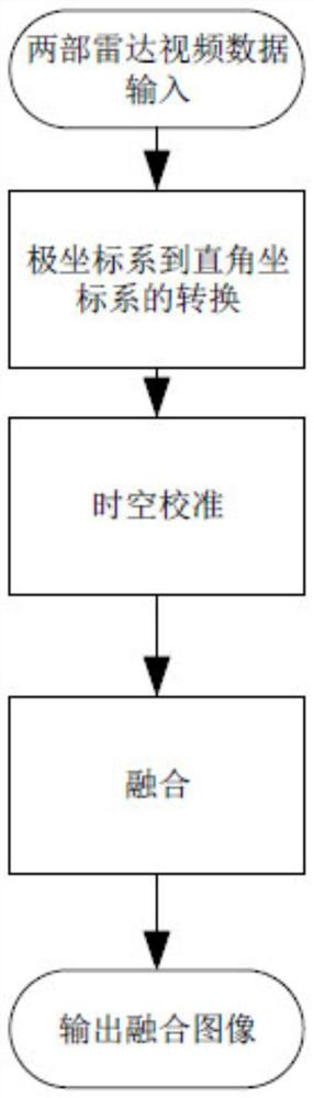
[0029] Specific implementation mode one: refer to figure 1 This embodiment is specifically described. A joint detection method for marine targets based on marine radar information fusion described in this embodiment includes the following steps:
[0030] Step 1: Obtain two radar videos;
[0031] Step 2: Obtain the polar coordinate systems corresponding to the two radar videos, and convert the polar coordinate system into a rectangular coordinate system;
[0032] Step 3: Put the two radar videos from their respective Cartesian coordinate systems to the consistent reference point CCRP Cartesian coordinate system;
[0033] Step 4: Use the fusion strategy to fuse the two radar videos under the consistent reference point CCRP Cartesian coordinate system;
[0034] Step 5: Output the fused image.
[0035] Ocean-going ships are generally equipped with two or more marine radar products. Therefore, making full use of the different blind spots of multiple marine radars to carry out ef...
specific Embodiment approach 2
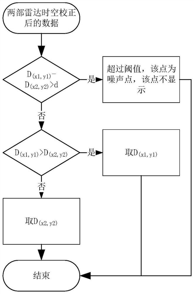
[0040] Specific embodiment 2: This embodiment is a further description of specific embodiment 1. The difference between this embodiment and specific embodiment 1 is that the fusion strategy includes dual radar co-display strategy, combined large display strategy, and combined small display strategy. Strategies and blind filling display strategies.
specific Embodiment approach 3
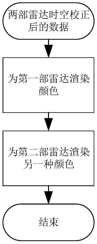
[0041] Embodiment 3: This embodiment is a further description of Embodiment 2. The difference between this embodiment and Embodiment 2 is that the steps for the fusion of the dual-radar co-display strategy are as follows:
[0042] First render a color for the first radar video, then render a different color for the second radar video than the first radar video and overlay it.
PUM
 Abstract
Description
Claims
Application Information