

System and method for transmitting aviation flight data and navigation information
A technology of flight data and navigation information, applied in data and information transmission system, aviation flight data and navigation information transmission system, aviation flight data and navigation information transmission field, can solve the problem of inaccurate positioning, limited display information, and overall pilot performance package. The problem of unsure of the line and margin, etc., to achieve the effect of accurate data, improve economic benefits, and ensure the safety of navigation
- Summary
- Abstract
- Description
- Claims
- Application Information
AI Technical Summary
Problems solved by technology
Method used
Image

Examples
Embodiment Construction
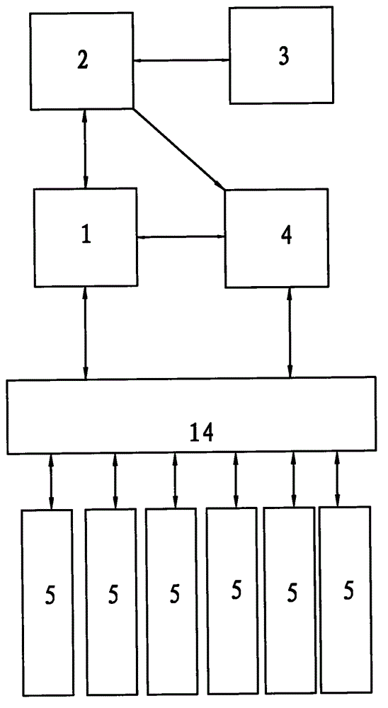
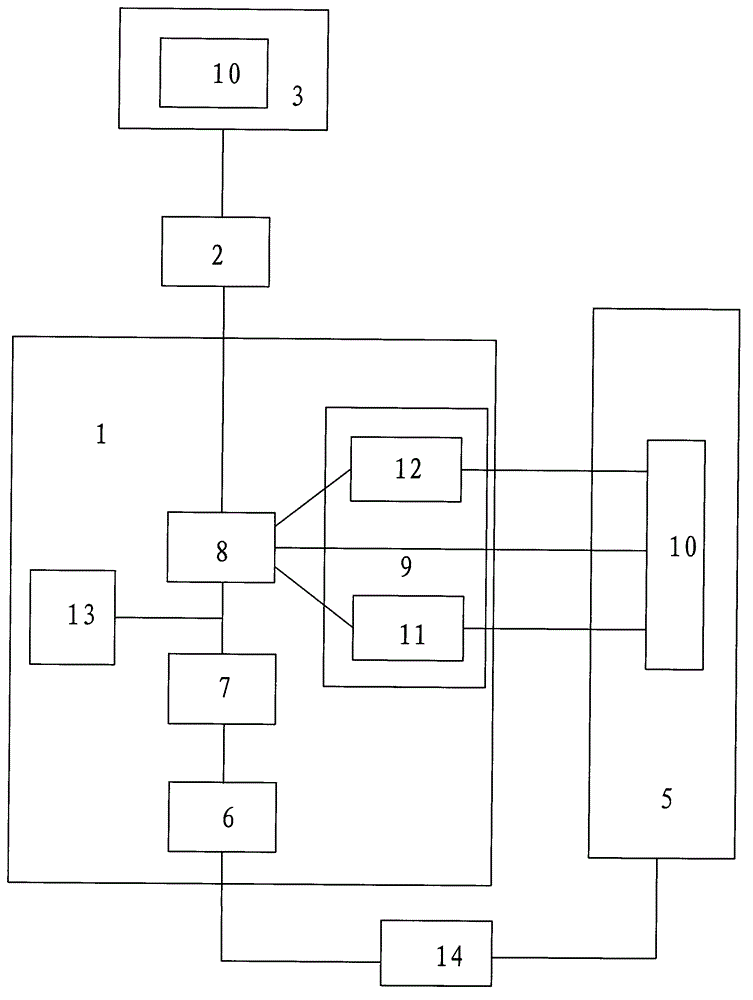
[0035] The following with attached Figure 1 to Figure 2 The aviation flight data and navigation information transmission system and method of the present invention are further described in detail.
[0036] For the aviation flight data and navigation information transmission system of the present invention, please refer to Figure 1 to Figure 2, including a data mining server 3, a database 2, a performance server 1, a system management server 4 and at least one mobile terminal 5, each of which is connected to the performance server 1 and the system management server 4, and the database 2 is connected to the system management server 4 respectively The performance server 1 is connected to the system management server 4 , the performance server 1 is connected to the system management server 4 , and the database 2 is connected to the data mining server 3 . In this way, compared to the prior art, the advantage is that the pilot can directly bring the mobile terminal 5 into the air...
PUM
 Abstract
Description
Claims
Application Information