
A Miniaturized Space Laser Communication Terminal Optical System and Using Method
An optical system and laser communication technology, applied in optics, optical components, transmission systems, etc., can solve the problems of complex structure and unfavorable miniaturization of a two-dimensional rotating optical system, and reduce assembly complexity, facilitate miniaturization, envelope small effect
- Summary
- Abstract
- Description
- Claims
- Application Information
AI Technical Summary
Problems solved by technology
Method used
Image

Examples
Embodiment
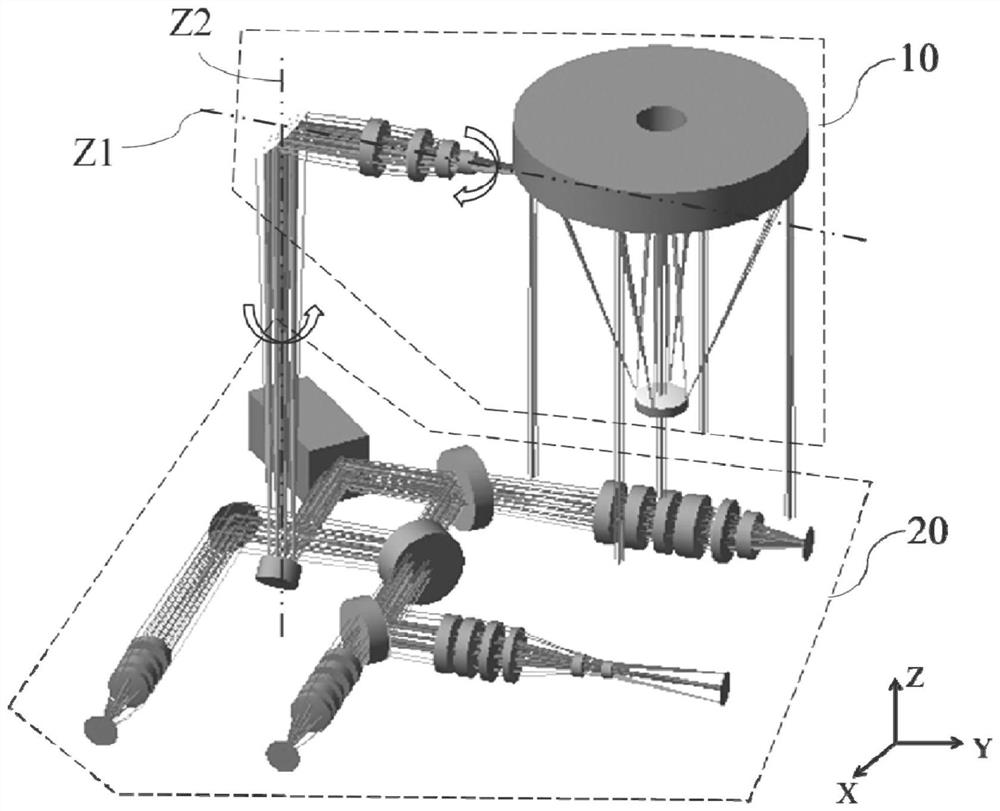
[0048] Such as figure 1 As shown, this embodiment provides a specific structure of a miniaturized space laser communication terminal optical system, including a telescope unit 10 and a relay optical path unit 20; the system constructs a pitch axis Z1 and an azimuth axis Z2;
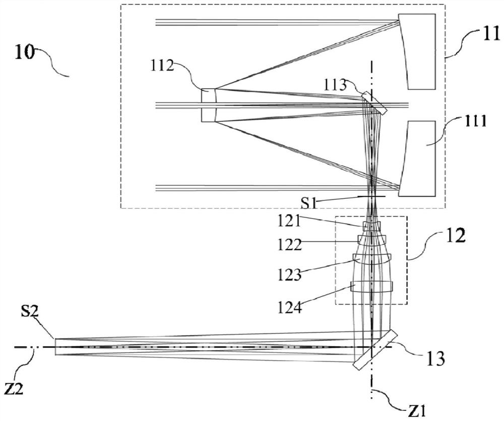
[0049] Such as figure 2 Shown is the telescope unit 10 provided by this embodiment. The telescope unit 10 includes a telescopic objective lens 11, an eyepiece 12, and a turntable folding axis mirror 13; the telescopic objective lens 11 and the eyepiece 12 are confocally arranged, and the confocal focal plane is marked as S1;
[0050]The telescopic objective lens comprises a main reflector 111, a secondary reflector 112, and a telescope folding mirror 113; the secondary reflector 112 is located on the reflected light path of the primary reflector 111, and the telescopic folded axis mirror 113 is located on the reflected light path of the secondary reflector 112; The main reflector 111 is an even-order as...
PUM
 Abstract
Description
Claims
Application Information