Magnetic ring internal crack detection device
A technology for detection devices and magnetic rings, applied in measuring devices, mechanical diameter measurement, instruments, etc., can solve the problems of lack of screening structure, lack of anti-drop structure, lack of waste removal structure, etc.
- Summary
- Abstract
- Description
- Claims
- Application Information
AI Technical Summary
Problems solved by technology
Method used
Image
Examples
Embodiment 1
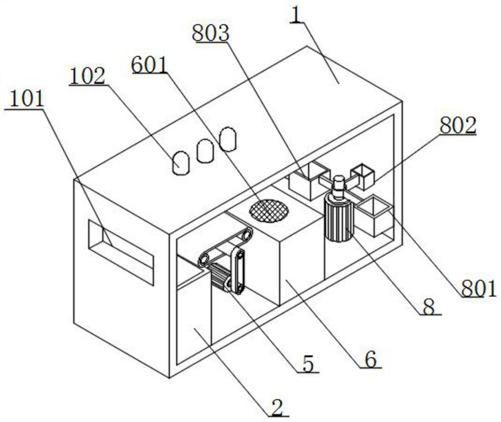
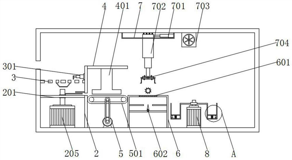
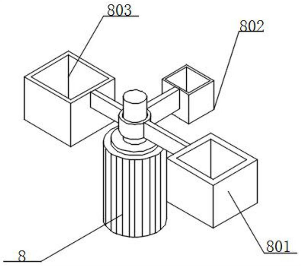
[0042] Example 1: See figure 1 and figure 2 , a magnetic ring internal crack detection device, comprising a main body 1, a feeding box 2, a placement table 6 and a fixed chute 7, the inner bottom wall of the main body 1 is equipped with a feeding box 2, and the inner wall of the feeding box 2 is equipped with a screening tray 3, and the screening tray 3 is located above the feeding tray 201, the outer wall of the feeding box 2 is equipped with a fixed plate 4, the inner bottom wall of the main body 1 is installed with a second motor 5, and the second motor 5 is located on the feeding box 2 One side of the main body 1 is equipped with a placement platform 6 on the inner bottom wall, and the placement platform 6 is located on one side of the second motor 5, the top of the main body 1 is equipped with a fixed chute 7, and the outer wall of the main body 1 is provided with a feeding hole 101 , three groups of warning lights 102 are installed on the top of the main body 1, the ma...
Embodiment 2
[0043] Example 2: see figure 2 and Image 6 , a magnetic ring inner crack detection device, the inner wall of the feeding box 2 is equipped with a feeding tray 201, the inner wall of the feeding tray 201 is equipped with a fixed protrusion 203, the outer wall of the feeding tray 201 is provided with a discharge hole 202, and the upper The inner wall of the material tray 201 is equipped with a limiting plate 204, the inner bottom wall of the upper material box 2 is equipped with a first motor 205, and the output end of the first motor 205 extends out of the top of the upper material tray 201, and the output end of the first motor 205 A push plate 206 is installed, a plurality of screening holes with different diameters are arranged on the top of the screening disc 3, a collecting tank is installed at the bottom of the screening disc 3, a first electric telescopic rod 301 is installed on the inner wall of the feeding box 2, and the first electric telescopic rod 301 One end of ...
Embodiment 3
[0044] Example 3: See figure 2 , a magnetic ring internal crack detection device, the top of the placement platform 6 is equipped with piezoelectric ceramics 601, the inner wall of the placement platform 6 is equipped with a detection board, the top of the detection board is equipped with a detection pointer 602, and the detection pointer 602 and the piezoelectric ceramics 601 is electrically connected through wires, two sets of trigger levers are installed on the inner wall of the placement table 6, three sets of transmission shafts are installed on the inner rear wall of the main body 1, and a conveyor belt 501 is installed around the outer wall of the transmission shaft, and the transmission shaft and the second motor 5 The output end is connected by a belt, the magnetic ring is discharged and enters the conveyor belt 501, the second motor 5 is started, the second motor 5 drives the belt to rotate, the belt drives the conveyor belt 501 to rotate, and the conveyor belt 501 d...
PUM
 Abstract
Description
Claims
Application Information
 - R&D
- Intellectual Property
- Life Sciences
- Materials
- Tech Scout
- Unparalleled Data Quality
- Higher Quality Content
- 60% Fewer Hallucinations
Browse by: Latest US Patents, China's latest patents, Technical Efficacy Thesaurus, Application Domain, Technology Topic, Popular Technical Reports.
© 2025 PatSnap. All rights reserved.Legal|Privacy policy|Modern Slavery Act Transparency Statement|Sitemap|About US| Contact US: help@patsnap.com


