Continuous numerical control pipe bending machine

A pipe bender and sliding connection technology, applied in safety equipment, feeding devices, positioning devices, etc., can solve the problems of low production efficiency, lack of continuity of the pipe bender, complicated operation steps, etc., to improve processing efficiency, Guaranteed stability and strong stability

Active Publication Date: 2021-11-09
南通驰连机械有限公司
View PDF8 Cites 1 Cited by
  • Summary
  • Abstract
  • Description
  • Claims
  • Application Information

AI Technical Summary

Problems solved by technology

[0005] Aiming at the deficiencies of the prior art, the present invention provides a continuous numerical control pipe bending machine, which solves a series of problems such as the pipe bending machine does not have continuity, the operation steps are cumbersome, and the production efficiency is low.

Method used


Image

  • Continuous numerical control pipe bending machine
  • Continuous numerical control pipe bending machine
  • Continuous numerical control pipe bending machine

Examples


Embodiment Construction

[0029] use Figure 1-Figure 6 A continuous numerical control pipe bending machine according to an embodiment of the present invention is described as follows.

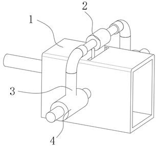
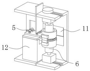
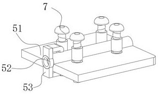
[0030] Such as Figure 1-Figure 6 As shown, a continuous numerical control pipe bending machine according to the present invention includes a processing box 1, which is characterized in that: the top of the inner cavity of the processing box 1 is provided with a cutting groove, and the top of the inner cavity of the processing box 1 is cut The groove is slidably connected with a vertical cutting blade 2, and the top of the vertical cutting blade 2 is fixedly connected with a moving sleeve arm 3, and the two ends of the inner wall of the moving sleeve arm 3 are slidably connected with an auxiliary shaft 4. The rear end of the auxiliary shaft 4 is fixedly connected to the front of the outer surface of the processing box 1 , and a thrust motor 13 is fixedly connected to one side of the outer surface of the auxiliary shaf...


PUM


Abstract

The invention belongs to the field of pipe machining, and particularly relates to a continuous numerical control pipe bending machine which comprises a machining box, wherein a cutting groove is formed in the top of an inner cavity of the machining box, a vertical cutting blade is slidably connected to the top of the inner cavity of the machining box through the cutting groove, a movable sleeve arm is fixedly connected to the top end of the vertical cutting blade, auxiliary shaft rods are slidably connected to the two ends of the inner wall of the movable sleeve arm correspondingly, the rear ends of the auxiliary shaft rods are fixedly connected to the front face of the outer surface of the machining box, and thrust motors are fixedly connected to the front faces of the outer surfaces of the auxiliary shaft rods. Due to the fact that the steel pipe is bent through the torque device, the steel pipe can be machined into an annular pipe and even a bent pipe with a more special angle, the shape and the bending angle of the steel pipe are more than those of a steel pipe machined through a common pipe bending machine, and the machined pipe body flies out of the torque device under the inertia effect and is thus thrown into a collecting device beside, to complete automatic collection of the steel pipe, so that the device has continuity.

Description

technical field [0001] The invention belongs to the field of pipe material processing, in particular to a continuous numerical control pipe bending machine. Background technique [0002] The pipe bender refers to the machine used for pipe bending and can also be used as a jack. It is roughly divided into CNC pipe bender, hydraulic pipe bender, etc. It is used in electric power construction, highway and railway construction, bridges, ships and other aspects of pipeline laying and repairing. Pipe benders can be roughly divided into CNC pipe benders, hydraulic pipe benders, etc. They are mainly used for laying and repairing pipes in electric power construction, highway and railway construction, boilers, bridges, ships, furniture, decoration, etc. Reasonable structure, simple operation, etc. In addition to the function of pipe bending, the pipe bender can also use the oil cylinder as a hydraulic jack. Compared with CNC pipe bending equipment, it has the characteristics of cheap ...

Claims


Application Information

Patent Timeline
Patent Type & Authority Applications(China)
IPC IPC(8): B21D7/024B21D7/12B21D43/28B21D43/20B21D55/00
CPCB21D7/024B21D7/12B21D43/285B21D43/20B21D55/00
Inventor 李靖
Owner 南通驰连机械有限公司
Why Eureka
Try Eureka