Forming mold for U-shaped spring

A forming mold and U-shaped technology, applied in the field of U-shaped spring forming molds, can solve problems such as safety accidents, non-perpendicular sides and bottoms, affecting product force value performance, etc., and achieve the effect of avoiding safety accidents.

Pending Publication Date: 2021-11-09
上海核工碟形弹簧制造有限公司
View PDF0 Cites 0 Cited by
  • Summary
  • Abstract
  • Description
  • Claims
  • Application Information

AI Technical Summary

Problems solved by technology

The role of the roller is actually to guide and adjust the opening distance of the U-shaped spring when the U-shaped spring is formed, and to reduce the static friction between the spring steel strip and the lower mold. Since the roller is fixed as a whole, it can only rotate itself. The disadvantages are: 1. The distance between the rollers on both sides directly affects the distance between the U-shaped springs after forming, and the distance after forming directly affects the key factors whether the spring meets the requirements of the process force value. If the distance between the rollers is too small, it will cause The thickness of the U-shaped spring is squeezed, and the thickness becomes thinner, which affects the force performance of the product. If the distance is too large, the two sides of the U-shaped spring are not perpendicular to the bottom after forming, and become a "horn" shape. 2. When forming a horn shape after forming, test the force. When the value is high, it will increase the risk of the product detaching from the test tool, resulting in a safety accident

Method used


Image

  • Forming mold for U-shaped spring
  • Forming mold for U-shaped spring
  • Forming mold for U-shaped spring

Examples


Embodiment Construction

[0019] In order for those skilled in the art to further understand the features and technical content of the present invention, please refer to the following detailed description and accompanying drawings of the present invention.

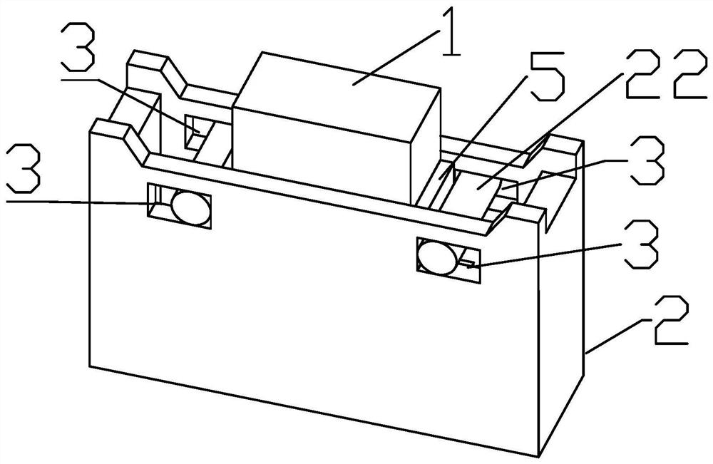
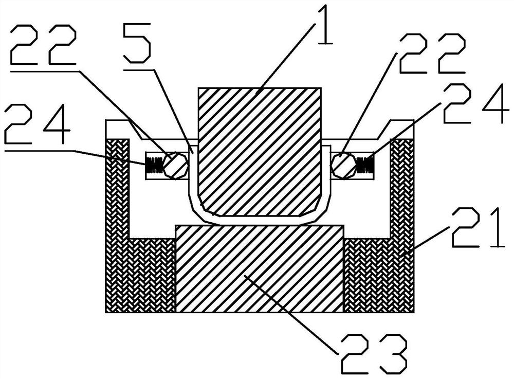
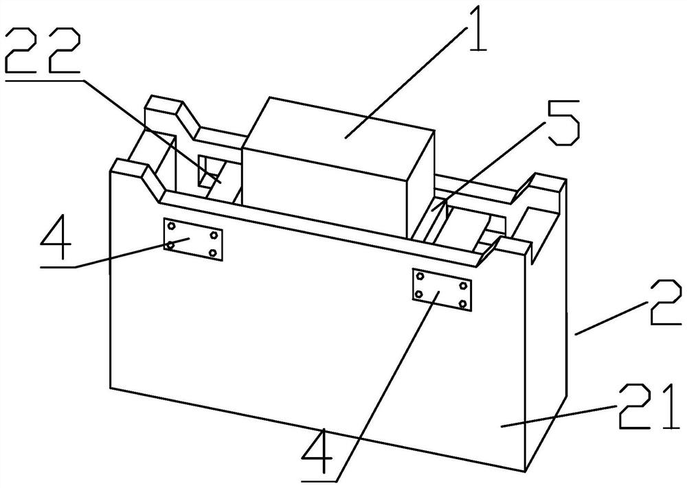
[0020] Such as Figure 1-3 Shown, a kind of forming mold of U-shaped spring comprises upper mold 1 and lower mold 2, and lower mold comprises lower mold body 21, forming roller 22, lower mold protrusion 23, helical spring 24, and the inside of lower mold body 21 A molding cavity with an upper opening is formed, the upper mold 1 is arranged in the molding cavity, and the left and right sides of the lower mold body 21 near the top edge are respectively provided with two square holes 3, and the square holes 3 on the left and right sides are respectively The forming roller 22 is installed, and the forming roller 22 radially fits with the width of the square hole 3. The central axis of the forming roller 22 is perpendicular to the central axis of the co...


PUM


Abstract

The invention discloses a forming mold for a U-shaped spring. The forming mold comprises an upper die and a lower die, wherein the lower die comprises a lower die body, forming pin rollers, a lower die protruding block and a limiting spring; a forming cavity with an opening in the upper part is formed in the lower die body; the upper die is arranged in the forming cavity; two square holes are formed in the left side and the right side, close to the top edge, of the lower die body respectively; the forming pin rollers are arranged in the square holes in the left side and the right side respectively; and the sides, away from the middle of the lower die body, of the forming pin rollers are connected with limiting springs, and the other ends of the corresponding limiting springs are fixed to the side ends of the lower die body on the corresponding sides. According to the U-shaped spring manufactured through the method, the thickness of the formed U-shaped spring cannot be reduced, and the product force value performance of the U-shaped spring is prevented from being affected; and the U-shaped spring is prevented from being trumpet-shaped after being formed, the risk that a product is separated from a test tool when a force value is tested is prevented, and safety accidents are prevented.

Description

technical field [0001] The invention relates to a spring molding device, in particular to a U-shaped spring molding die. Background technique [0002] The existing U-shaped spring forming mold roller is fixed as a whole, and only rubs against the raw material during forming to generate rotation. The role of the roller is actually to guide and adjust the opening distance of the U-shaped spring when the U-shaped spring is formed, and to reduce the static friction between the spring steel strip and the lower mold. Since the roller is fixed as a whole, it can only rotate itself. The disadvantages are: 1. The distance between the rollers on both sides directly affects the distance between the U-shaped springs after forming, and the distance after forming directly affects the key factors whether the spring meets the requirements of the process force value. If the distance between the rollers is too small, it will cause The thickness of the U-shaped spring is squeezed, and the thi...

Claims


Application Information

Patent Timeline
Patent Type & Authority Applications(China)
IPC IPC(8): B21F1/00
CPCB21F1/004
Inventor 李龙周兴友袁大传徐杰
Owner 上海核工碟形弹簧制造有限公司
Why Eureka
Try Eureka