Rail transit sand scattering device

A rail transit and buffer device technology, which is applied in the field of rail transit, can solve the problems such as the inability to realize the movement and mixing of sand at different height layers, and achieve the effect of facilitating precise control, avoiding water accumulation and agglomeration, and improving uniformity

Active Publication Date: 2021-11-09
CHECC DATA CO LTD +2
View PDF5 Cites 0 Cited by
  • Summary
  • Abstract
  • Description
  • Claims
  • Application Information

AI Technical Summary

Problems solved by technology

[0005] Aiming at the deficiencies of the prior art, the present invention provides a sanding device for rail transit, which solves the problem that the existing sanding device cannot realize the mobile mixing of sanding at different height layers, and can avoid sanding and water accumulation at the bottom layer, Improve the buffering capacity of the device, reduce the wear and tear on the inner wall of the device by sanding, improve the service life of the device, realize the crushing treatment of sanding, and avoid sanding and agglomeration from adhering to the inner wall of the device

Method used


Image

  • Rail transit sand scattering device
  • Rail transit sand scattering device
  • Rail transit sand scattering device

Examples


Embodiment 1

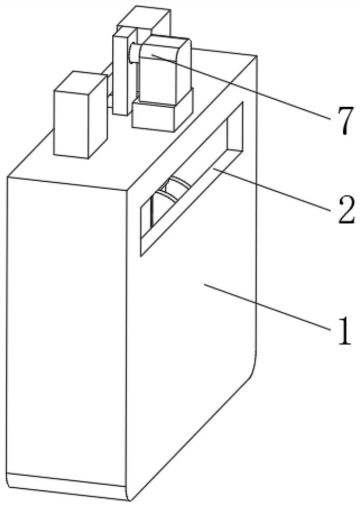
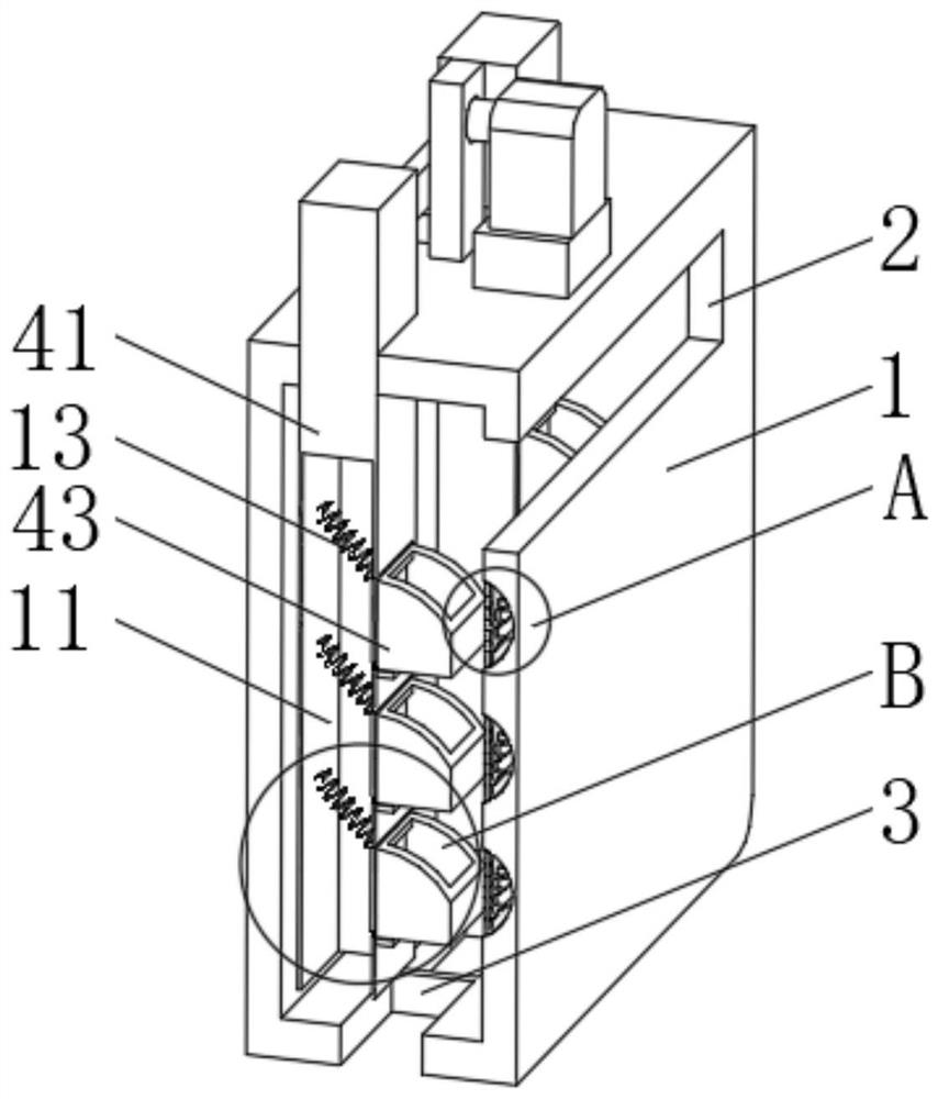
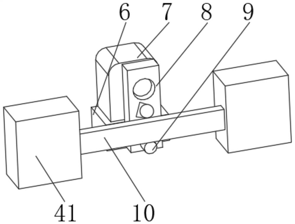
[0032] see Figure 1-6 , the present invention provides a technical solution: a rail transit sand spreading device, comprising a storage bin 1, one side of the storage bin 1 is provided with a feed port 2, and the bottom of the feed port 2 is provided with a discharge port 3, The interior of the storage bin 1 is provided with a refueling device 4, the refueling device 4 has a lifting plate 41, the lifting plate 41 runs through the storage bin 1 and extends to the outside of the storage bin 1, one side of the lifting plate 41 is evenly installed with limited The position plate 42 and the top of the limit plate 42 are rotatably connected with a turning box 43 , and the top of the turning box 43 is provided with a feeding port 44 .

[0033] The top of the storage bin 1 is fixedly connected with a backing plate 6, the top of the backing plate 6 is fixedly connected with a refueling motor 7, and the output end of the refueling motor 7 is fixedly connected with a rotating plate 8, a...

Embodiment 2

[0040] see Figure 1-6 , the present invention provides a technical solution: on the basis of Embodiment 1, a buffer device 5 is provided inside the storage bin 1, and the buffer device 5 has a buffer tank 51, and the buffer tank 51 is set on the inner wall of the storage bin 1. On the side, an elastic membrane 52 is fixedly connected between both sides of the inner wall of the buffer tank 51 , and a wear-resistant plate 53 is evenly installed on the side of the elastic membrane 52 close to the flip box 43 .

[0041] A support spring plate 54 is fixedly connected to one side of the inner wall of the buffer tank 51 , and the support spring plate 54 is connected to the elastic film 52 in a sliding manner.

[0042] When in use, the supporting elastic plate 54 pushes the elastic film 52 and the wear plate 53 to the outside of the buffer tank 51, the lifting plate 41 and the flip box 43 lift and push the sand to move to the inner wall of the storage bin 1, and the wear plate 53 is ...


PUM


Abstract

The invention discloses a rail transit sand scattering device which comprises a storage bin, a feeding port is formed in one side of the storage bin, a discharging port is formed in the bottom of the feeding port, a material changing device is arranged in the storage bin, the material changing device is provided with a lifting plate, and the lifting plate penetrates through the storage bin and extends out of the storage bin; and a buffering device which has a buffering groove, the buffering groove is formed in one side of the inner wall of the storage bin, and an elastic film is fixedly connected between the two sides of the inner wall of the buffering groove. According to the rail transit sand scattering device, the purpose of moving and mixing scattered sand of different height layers is achieved, water accumulation and caking of scattered sand at the bottom layer can be avoided, the buffering capacity of the device is improved, abrasion of scattered sand to the inner wall of the device is reduced, the service life of the device is prolonged, scattered sand can be crushed, and scattered sand caking is prevented from being attached to the inner wall of the device.

Description

technical field [0001] The invention relates to the technical field of rail transit, in particular to a sand spreading device for rail transit. Background technique [0002] Railway transportation uses traction and brake adhesion friction generated by wheel-rail interaction to realize the operation of trains. With the construction of high-speed railways, the traction load of electric locomotives is increasing day by day. Improving the adhesion performance of locomotives has become a crucial issue. Sand spreading is the equipment of railway vehicles. The purpose is to use sand to increase the friction between the wheel and the rail, shorten the braking distance and increase the friction of climbing. [0003] However, the existing sanding device cannot realize the moving and mixing of sanding at different height layers, and cannot avoid agglomeration of sand and accumulated water at the bottom layer. The buffering effect is poor, and the wear of sanding on the inner wall of th...

Claims


Application Information

Patent Timeline
Patent Type & Authority Applications(China)
IPC IPC(8): B61C15/10B65G69/14B65G65/40B65G65/32
CPCB61C15/10B65G69/14B65G65/40B65G65/32B65G2201/045
Inventor 况雨昕
Owner CHECC DATA CO LTD
Why Eureka
Try Eureka