
A flue gas treatment burner for flue gas purification and cleaning

A flue gas treatment and flue gas purification technology, applied in the field of flue gas treatment, can solve problems such as poor burner purification effect, and achieve the effects of increasing speed, increasing rotational speed, and improving purification effect

Active Publication Date: 2022-04-05
WUXI WANFANG ENERGY EQUIP CO LTD
View PDF13 Cites 0 Cited by
  • Summary
  • Abstract
  • Description
  • Claims
  • Application Information

AI Technical Summary

Problems solved by technology

[0006] The purpose of the present invention is to overcome the problem of poor purification effect of the burner in the prior art, meet the actual needs, and provide a flue gas treatment burner for flue gas purification and cleaning, so as to solve the above technical problems

Method used


Image

  • A flue gas treatment burner for flue gas purification and cleaning
  • A flue gas treatment burner for flue gas purification and cleaning
  • A flue gas treatment burner for flue gas purification and cleaning

Examples


Embodiment Construction

[0032] The following will clearly and completely describe the technical solutions in the embodiments of the present invention with reference to the accompanying drawings in the embodiments of the present invention. Obviously, the described embodiments are only some, not all, embodiments of the present invention.

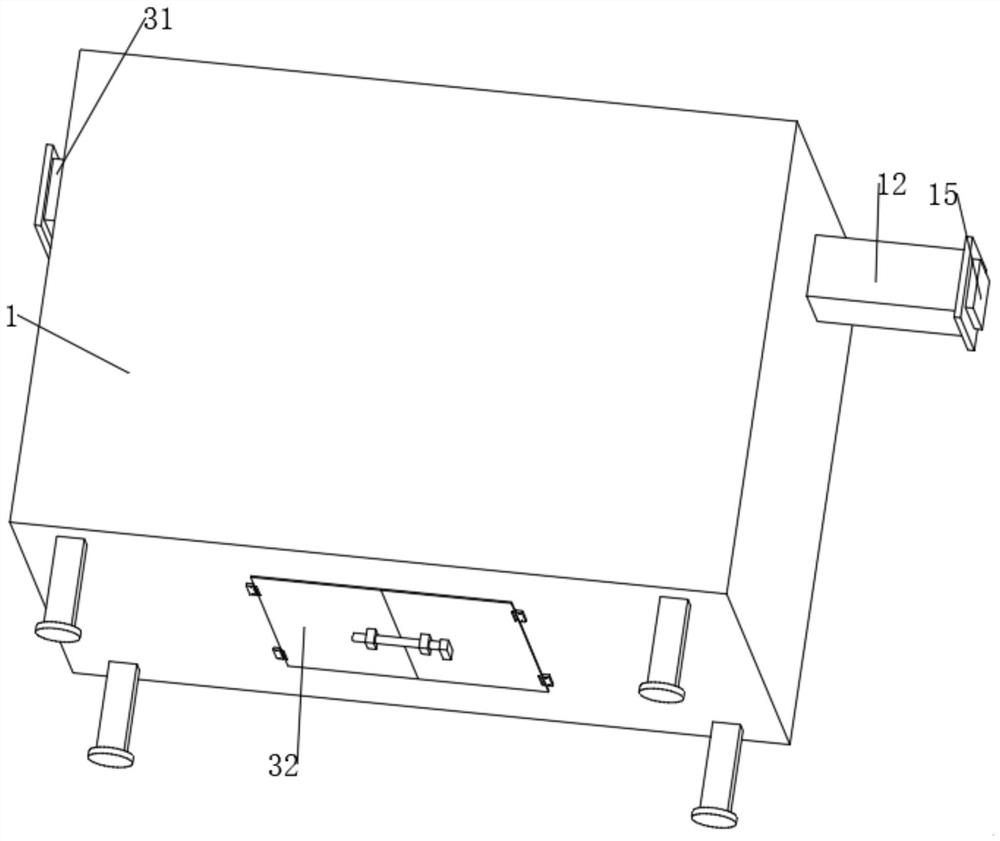
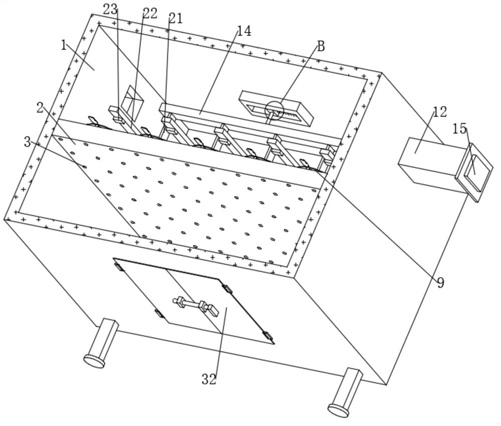
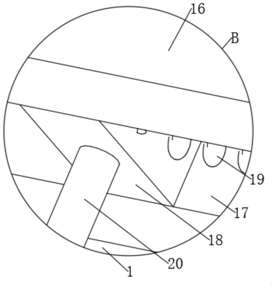
[0033] Attached below Figure 1-8 The present invention is further described with embodiment:

[0034] In this example, if Figure 1-5 As shown, a flue gas treatment burner for flue gas purification and cleaning includes a combustion box 1. A partition 2 is fixed in the combustion box 1 by bolts. The top of the partition 2 is provided with dense through holes 3. The top of the partition 2 There are multiple groups of evenly distributed installation grooves 4, the bottom inner wall of the installation groove 4 is fixed with a return spring 5 by bolts, the top of the return spring 5 is fixed with a top block 6 by bolts, and the top of the top block 6 is connected with...


PUM


Abstract

The invention relates to a flue gas treatment burner for flue gas purification and cleaning, comprising a combustion box, a baffle plate is fixed in the combustion box, a plurality of sets of installation grooves are arranged on the top of the baffle plate, and a reset spring is fixed on the inner wall of the bottom of the installation groove, which can be reset. A top block is fixed on the top of the spring, a connecting shaft is rotatably connected to the top of the top block, a collar is sleeved and fixed on the top of the connecting shaft, a plurality of pushing blades are fixed on the circumferential outer wall of the collar, a second permanent magnet is fixed in the top block, and the combustion box is A strip is fixed on the inner wall of the top, a first chute is opened at the bottom of the strip, a first slider is slidably connected in the first chute, a first spring is fixed between the first slider and the inner wall of the first chute, and the first A first connecting rod is fixed at the bottom of the slider, and a plunger is fixed at the bottom of the first connecting rod; the present invention uses the rotating pusher blade to drive the ash and impurities to move, thereby accelerating the ash falling from the through hole, and making the impurities burn again, Therefore, the impurities are fully burned, and the purification effect of the device is improved.

Description

technical field [0001] The invention relates to the technical field of flue gas treatment, in particular to a flue gas treatment burner for flue gas purification and cleaning. Background technique [0002] The flue gas treatment equipment is to effectively treat the toxic and harmful substances contained in the flue gas to below the specified concentration, and avoid corrosion or blockage of the equipment. Generally, the flue gas treatment equipment used in waste incineration plants is divided into two categories: dust removal equipment and acid gas removal equipment. Now, with the improvement of people's requirements for environmental quality, most waste incineration plants have added activated carbon adsorption heavy metal equipment in the flue gas treatment process. [0003] In the asphalt waste gas treatment technology, because there are many impurity particles in the asphalt waste gas, it is extremely polluting to the air ring, and if inhaled into the human body, it wi...

Claims


Application Information

Patent Timeline
Patent Type & Authority Patents(China)
IPC IPC(8): F23G7/06F23J1/06H02K35/02
CPCF23G7/06F23J1/06H02K35/02Y02E20/12
Inventor 董欣宇曹宪清
Owner WUXI WANFANG ENERGY EQUIP CO LTD
Learn More