Vertical Active Lime Calciner

A technology of active lime and calciner, applied in the field of vertical active lime calciner and lime shaft kiln, can solve the problems of energy loss and environmental pollution, high production cost, difficult to guarantee product quality, etc., and achieve smooth continuous feeding. , The quality of calcined products is stable, and the effect of reducing the height of the equipment

Active Publication Date: 2019-04-30
山西奋达机械制造有限公司
View PDF6 Cites 0 Cited by
  • Summary
  • Abstract
  • Description
  • Claims
  • Application Information

AI Technical Summary

Problems solved by technology

However, this calcination method has high raw material coal consumption, low thermal efficiency, serious energy loss and environmental pollution, requires manual continuous monitoring operations, low production efficiency and high labor costs, and due to unstable operating conditions, over-burning and under-burning occur from time to time. , the product quality is difficult to guarantee, and the production cost remains high
Moreover, the existing calcination furnace uses a single fuel, and one kind of calcination furnace is only suitable for a specific fuel, so the fuel cannot be shared.

Method used


Image

  • Vertical Active Lime Calciner
  • Vertical Active Lime Calciner
  • Vertical Active Lime Calciner

Examples


Embodiment 1

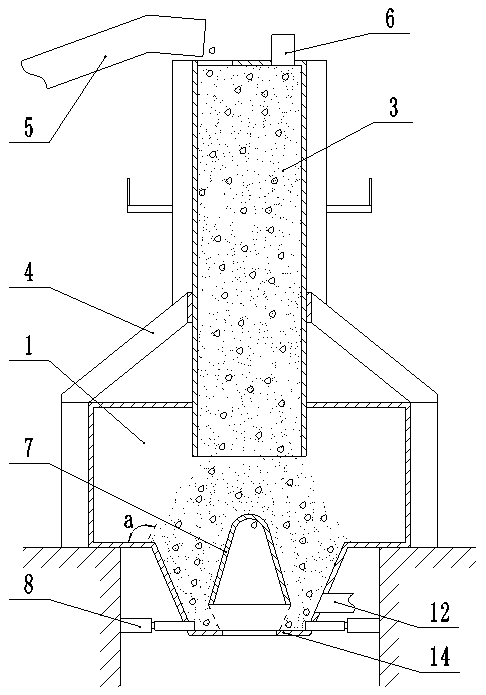
[0031] Such as figure 1 , Figure 4-7 As shown, the vertical active lime calciner includes an outer combustion chamber 1, a fuel injection pipeline 2, a kiln body 3, a suspension 4, a conveyor belt 5, a negative pressure induced fan 6, a hydraulic discharge device 8 and a control system. The structure of the chamber 1 is that the bottom of the cylindrical furnace body is provided with a funnel-shaped cooling section. The furnace body of the outer combustion chamber 1 is fixedly installed on the ground and its cooling section is located in the pit. The fuel injection pipeline 2, the kiln body 3 is fixedly arranged above the outer combustion chamber 1 through the suspension bracket 4, the kiln body 3 is a cylindrical shape with an open lower end and its lower end extends into the interior of the furnace body, and the upper wall of the furnace body Sealed connection with the outer wall of the kiln body 3, the top of the kiln body 3 is provided with a feed port and the discharge ...

Embodiment 2

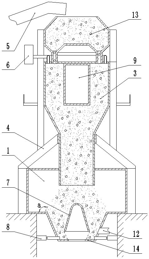
[0038] Such as figure 2 As shown, on the basis of Example 1, the upper part of the kiln body 3 is a preheating section and the lower part is a calcining section, the diameter of the preheating section is larger than the calcining section, and the preheating section and the calcining section pass through Conical transition seal connection.

[0039] A hollow cylinder 9 is fixed in the center of the preheating section of the kiln body 3 .

[0040] Above the kiln body 3, there is a process silo 13, the lower part of the process silo 13 communicates with the upper part of the kiln body 3 through an annular pipe and supplies materials to the kiln body 3, and the discharge end of the conveyor belt 5 corresponds to the process material Storehouse 13 feeding ports.

[0041] The inner bottom surface of the process silo 13 is provided with a conical protrusion, and the annular pipe communicating with the upper part of the kiln body 3 is arranged at the lowest point around the conical ...

Embodiment 3

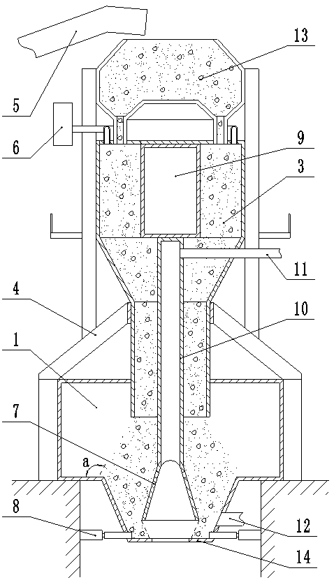
[0045] Such as image 3 As shown, on the basis of Embodiment 2, a cylindrical inner combustion chamber 10 is vertically arranged in the center of the kiln body 3 and the lower end of the inner combustion chamber 10 is open, and the upper part of the inner combustion chamber 10 communicates with Internal combustion pipeline 11 is arranged.

[0046] The lower end of the internal combustion chamber 10 communicates with the inside of the material retaining platform 7 and the side wall of the material retaining platform 7 is evenly provided with a plurality of air outlet holes, so that the combustion fuel in the internal combustion chamber 10 can evenly overflow.

[0047] This embodiment is suitable for large-scale calcination with a large diameter kiln body, double-stage combined calcination, to avoid incomplete calcination at the center of the kiln body, which affects product quality, and the working process is similar to the second embodiment, but the internal combustion pipelin...


PUM


Abstract

The invention relates to a vertical type active lime calcining furnace, belongs to the technical field of industrial furnaces and provides a vertical type active lime calcining furnace which can calcine continuously, has high production efficiency and stable calcining quality and saves production cost and labor cost. The vertical type active lime calcining furnace is characterized in that a funnel-shaped cooling section is arranged at the bottom of a furnace body, an external combustion chamber of the furnace body is in a cylindrical shape, a fuel spraying pipeline is arranged on a lateral wall of the furnace in the tangent direction, the lower end of a kiln body extends into the furnace body, a feeding opening and a negative-pressure induced draft fan are arranged on the kiln body, materials falling from the kiln body can stack in the cooling section to form a repose angle, a material stopping bench in the external combustion chamber is arranged right under the kiln body, a plurality of blanking clearances are formed between the bottom of the material stopping bench and a lateral wall of the cooling section, an outlet in the lower portion of the cooling section is provided with an annular material stopping plate with a blanking hole in the center, materials can fall on the annular material stopping plate from the plurality of blanking clearances to form repose angles, and a plurality of hydraulic discharging devices corresponding to the blanking clearances are arranged at the periphery of the lower portion of the cooling section. The vertical type active lime calcining furnace disclosed by the invention can feed materials automatically and calcine continuously.

Description

technical field [0001] The invention relates to a vertical active lime calciner, which belongs to the technical field of industrial furnaces and kilns, and in particular relates to a lime shaft kiln. Background technique [0002] In the prior art, lime preparation is usually calcined in a horizontal rotary kiln, or intermittently calcined in a single vertical kiln. Every time a furnace of lime is produced, it has to go through the operation steps of kiln installation-calcination-out of the kiln. And when the kiln is installed, the raw materials and coal ash are mixed and filled into the kiln, and the lime is calcined by burning the coal ash. However, this calcination method has high raw material coal consumption, low thermal efficiency, serious energy loss and environmental pollution, requires manual continuous monitoring operations, low production efficiency and high labor costs, and due to unstable operating conditions, over-burning and under-burning occur from time to ti...

Claims


Application Information

Patent Timeline
Patent Type & Authority Patents(China)
IPC IPC(8): C04B2/12
CPCC04B2/12Y02P40/40
Inventor 师武军张应廷
Owner 山西奋达机械制造有限公司
Why Eureka
Try Eureka