A garden waste recycling machine

A garden waste and feeder technology, which is applied in the field of waste treatment, can solve the problems of poor crushing effect of the chemical feeder, achieve the effects of improving the crushing effect, preventing material blocking, and increasing the contact area

Active Publication Date: 2022-02-01
国家煤化工产品质量监督检验中心
View PDF4 Cites 0 Cited by
  • Summary
  • Abstract
  • Description
  • Claims
  • Application Information

AI Technical Summary

Problems solved by technology

[0004] Based on the technical problem that the crushing effect of the existing chemical material machine is not good, the present invention proposes a garden waste chemical material machine

Method used


Image

  • A garden waste recycling machine
  • A garden waste recycling machine
  • A garden waste recycling machine

Examples


Embodiment 1

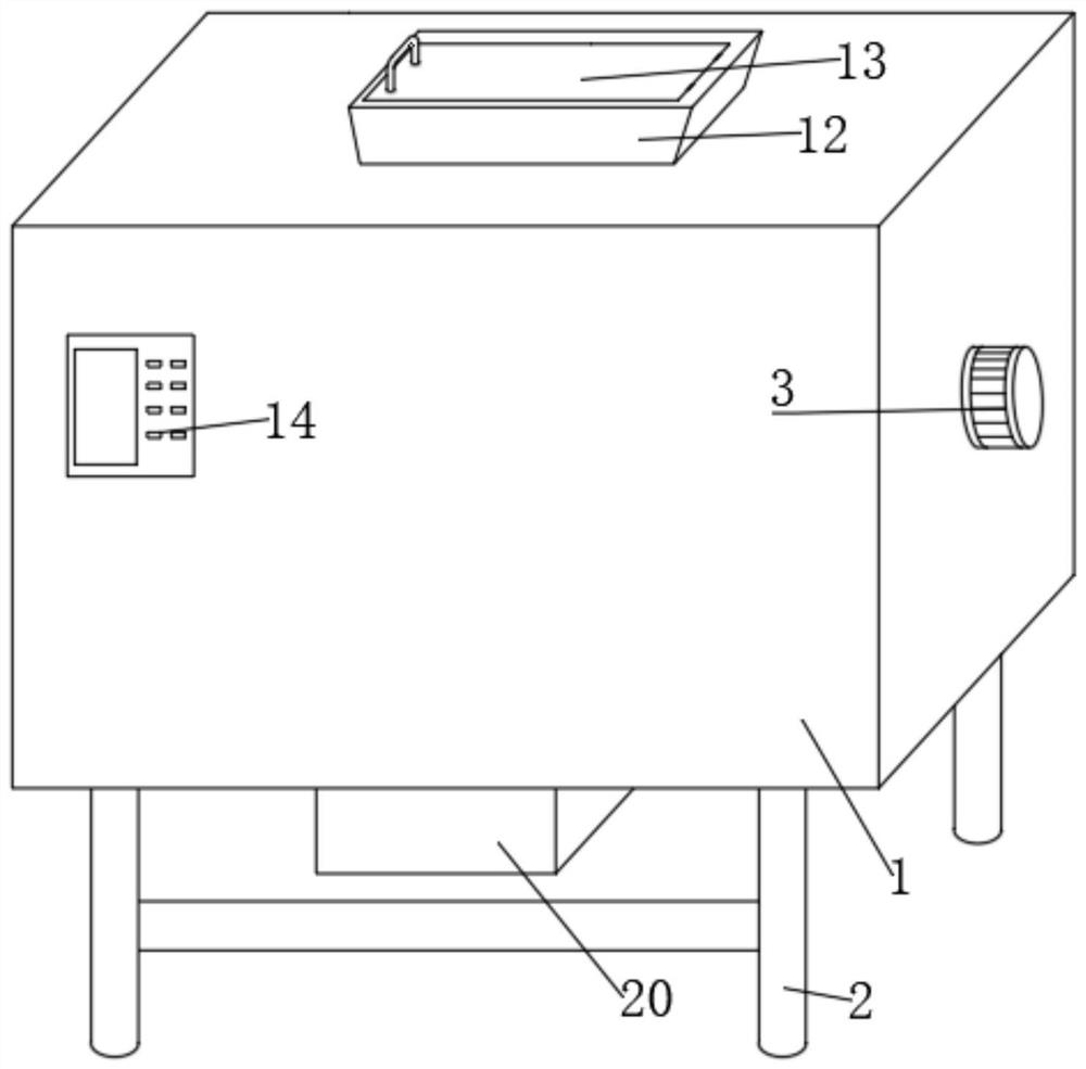
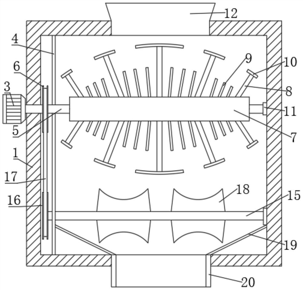
[0028] refer to Figure 1-3 , a garden waste chemical machine, comprising a box body 1, a plurality of legs 2 are symmetrically fixed on both sides of the bottom of the box body 1 by bolts, a motor 3 is fixed on one side of the box body 1 by bolts, and the output shaft of the motor 3 is connected with a first The straight shaft 5, the inner side of the first straight shaft 5 protrudes into the box body 1, and the bearing 11 is nested and fixed, and the other side of the bearing 11 is fixedly connected with the inner wall of the box body 1 by bolts, and the first straight shaft 5 is sleeved and fixed with a rotating roller 7. A plurality of first crushing rods 8 and second crushing rods 9 are fixed on the outer wall of the circumference of the rotating roller 7 by bolts. The plurality of first crushing rods 8 and the second crushing rods 9 all form a rugby ball shape, and the first crushing rods 8 The density is less than that of the second crushing rod 9, the length of the fir...

Embodiment 2

[0032] refer to Figure 1-5 , a kind of garden waste feeder, a plurality of connecting rods 26 uniformly distributed in the transverse direction are fixed by bolts between the inner walls of the two ends of the feeding trough plate 12, and the connecting rods 26 are sleeved with a material distribution plate 25, and a plurality of material distribution plates 25 is distributed and inclined, and the inner wall of the rear end of the feed trough plate 12 is provided with a plurality of second chute 27, the cross section of the second chute 27 is arranged in an arc shape, and the second chute 27 is slidably connected with a second slider. The second slide block is fixedly connected with the distribution plate 25, the bottom of the second slide block is fixed with a second spring 28 by bolts, and the bottom of the second spring 28 is welded and fixed to the inner wall of the second chute 27.

[0033] When in use, a plurality of material distribution plates 25 are inclined in a dis...


PUM


Abstract

The present invention belongs to the technical field of waste treatment, in particular to a garden waste composting machine. Aiming at the problem of poor crushing effect of the existing chemical composting machine, the following scheme is proposed, including a box body, and a motor is fixed on one side of the box body , the motor is connected with a first straight shaft, a bearing is fixed inside the first straight shaft, a rotating roller is fixed on the first straight shaft, and a plurality of first crushing rods and second crushing rods are fixed on the outer wall of the rotating roller circumference, and a plurality of first crushing rods are fixed on the outer wall of the rotating roller. Both the crushing rod and the second crushing rod are in the shape of a rugby ball, the length of the first crushing rod is greater than that of the second crushing rod, and a sweeping plate is arranged on the top of the first crushing rod. In the present invention, the motor drives the first crushing rod, the second crushing rod and the sweeping plate to rotate, and a plurality of the first crushing rods and the second crushing rods all form a rugby ball shape, so that the sweeping plate and the first crushing rod will be larger The crushed waste will fall into the dense second crushing rod area for secondary crushing, thereby improving the crushing effect.

Description

technical field [0001] The invention relates to the technical field of waste treatment, in particular to a garden waste materializer. Background technique [0002] Plant materials such as tree and shrub trimmings, lawn trimmings, fallen leaves, branches, discarded grass flowers and weeds in gardens and flower beds produced during the natural or maintenance process of green plants in urban green land or suburban woodland, currently Beijing, Shanghai, Guangzhou and Shenzhen and other large and medium-sized cities have begun to collect, crush, and compost green plant waste in a unified manner. After slicing or crushing, they are processed into mulch, organic substrate, and organic fertilizer for landscaping soil improvement. [0003] In the process of crushing waste, the motor is generally used to drive the direct shaft to rotate, which drives the crushing rod to rotate and then crush the waste added into the box. However, the existing crushing rods are generally distributed ne...

Claims


Application Information

Patent Timeline
Patent Type & Authority Patents(China)
IPC IPC(8): B02C13/06B02C13/28B02C13/286B02C13/30B02C23/02
CPCB02C13/06B02C13/2804B02C13/286B02C13/30B02C23/02B02C2013/28672B02C2201/06
Inventor 王曦赵勇李亚亮陈斌刘海涛吴广珍汪惠敏韩永友胡心亭郭冬灵
Owner 国家煤化工产品质量监督检验中心
Why Eureka
Try Eureka