Device and method for improving motion resolution of standing wave type piezoelectric ultrasonic motor
An ultrasonic motor and resolution technology, applied in the direction of generator/motor, piezoelectric effect/electrostrictive or magnetostrictive motor, electrical components, etc., can solve the problem of limited application of standing wave piezoelectric ultrasonic motor , to achieve the effect of improving motion resolution
- Summary
- Abstract
- Description
- Claims
- Application Information
AI Technical Summary
Problems solved by technology
Method used
Image
Examples
Embodiment 1
[0050] This embodiment provides a standing wave type piezoelectric ultrasonic motor motion resolution improvement device,
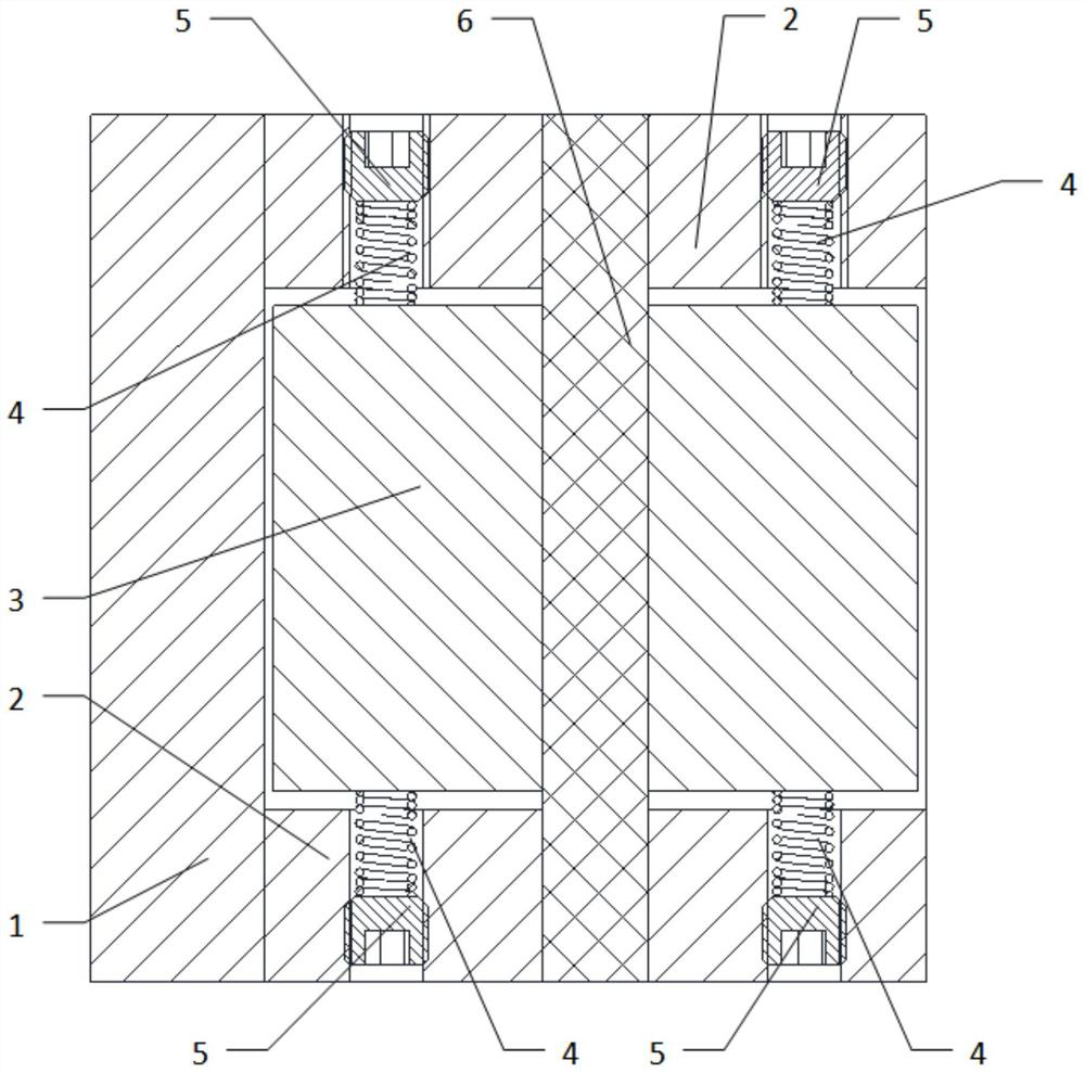
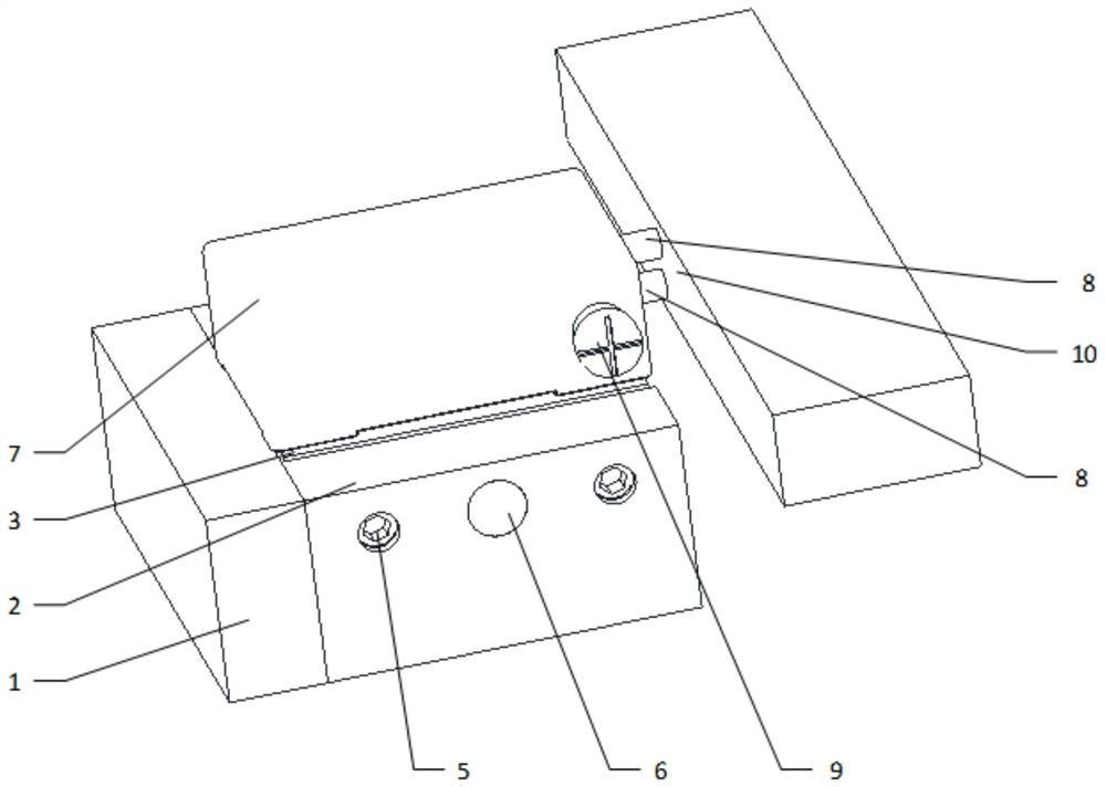
[0051] Such as Figure 2-3 As shown, the lifting device of this embodiment includes a mode switching device.
[0052] Wherein, the mode switching device is mainly composed of a holder 1 , a base 2 , a sliding seat 3 and a guide pin 6 .
[0053] The base 2 is fixedly installed on the stable structure of the motion system, the guide pin 6 is fixedly connected in the base 2, the slide seat 3 can move freely in the base 2 along the axial direction of the guide pin 6; the standing wave piezoelectric ultrasonic motor 7 Installed on the sliding seat 3; the holder 1 is used to realize the fixing and releasing of the sliding seat 3, so as to realize the switching of the motion state, so as to realize the motion resolution of the standing wave piezoelectric ultrasonic motor.
[0054] The mode switching device of this embodiment also includes an elastic element 4;...
Embodiment 2
[0063] In this embodiment, the holder 1 of the above-mentioned embodiment 1 is further optimized:
[0064] The clamper 1 of this embodiment adopts a pneumatic device, and the clamper 1 is equipped with two telescopic cylinders inside. After ventilation, the cylinders stretch out against the sliding seat 3, and the frictional force generated by the cylinders is greater than the frictional driving force of the piezoelectric ultrasonic motor 7 , when the driving foot 8 and the rotor 10 of the piezoelectric ultrasonic motor 7 move, the sliding seat 3 cannot move along the guide pin 6, and the sliding seat 3 and the base 2 will not move relative to each other; when the air circuit is disconnected, the cylinder shrinks Back, the sliding seat 3 is separated from the holder 1, and the sliding seat 3 can slide along the axial direction of the guide pin 6, so that the sliding seat 3 and the base 2 form relative motion.
[0065] Such as Figure 4 As shown, the device working process of ...
Embodiment 3
[0071] In this embodiment, the holder 1 and the sliding seat 3 of the above-mentioned embodiment 1 are further optimized:
[0072] The gripper 1 of this embodiment adopts an electromagnetic device, and an electromagnet is housed in the gripper 1, and the slide seat 3 is made of a ferromagnetic material. The attractive force is greater than the friction driving force of the motor, so that the sliding seat 3 cannot move relative to the base 2 when the motor moves. After the electromagnet is de-energized, the holder 1 is separated from the sliding seat 3, and the sliding seat 3 can slide along the axial direction of the guide pin 6, and then the sliding seat 3 and the base 2 form relative motion.
[0073] Such as Figure 5 As shown, the device working process of the present embodiment is as follows:
[0074] Power-on starts to execute motion commands, and automatically obtains signals and judges the motion of piezoelectric ceramic rotor 10 through feedback devices (sensor devic...
PUM
 Abstract
Description
Claims
Application Information
 - R&D
- Intellectual Property
- Life Sciences
- Materials
- Tech Scout
- Unparalleled Data Quality
- Higher Quality Content
- 60% Fewer Hallucinations
Browse by: Latest US Patents, China's latest patents, Technical Efficacy Thesaurus, Application Domain, Technology Topic, Popular Technical Reports.
© 2025 PatSnap. All rights reserved.Legal|Privacy policy|Modern Slavery Act Transparency Statement|Sitemap|About US| Contact US: help@patsnap.com


